Plasma generation module and air cleaner

An air purification device and plasma technology, applied in plasma, electrical components, deodorization, etc., can solve problems such as difficult to achieve surface glow plasma generation

Inactive Publication Date: 2018-07-24
BEIJING RUIYUDA TECH
View PDF9 Cites 4 Cited by
  • Summary
  • Abstract
  • Description
  • Claims
  • Application Information

AI Technical Summary

Problems solved by technology

[0004] However, the discharge mode generated by the existing creeping dielectric barrier discharge generators is mainly filamentary discharge, and it is difficult to realize the generation of surface glow plasma

Method used


Image

  • Plasma generation module and air cleaner
  • Plasma generation module and air cleaner
  • Plasma generation module and air cleaner

Examples


Embodiment 1

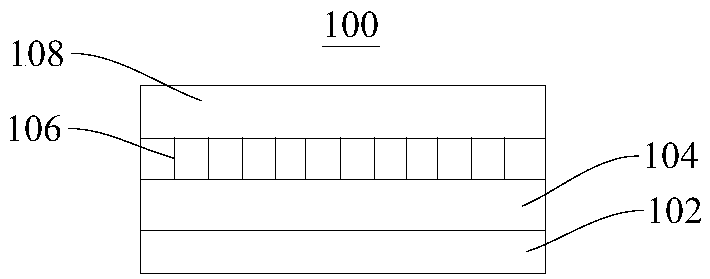
[0033] Please refer to figure 1 , figure 1 Shown is a schematic structural diagram of the plasma generating assembly 100 . The present embodiment provides a plasma generating assembly 100, which is mainly used for generating surface glow plasma.

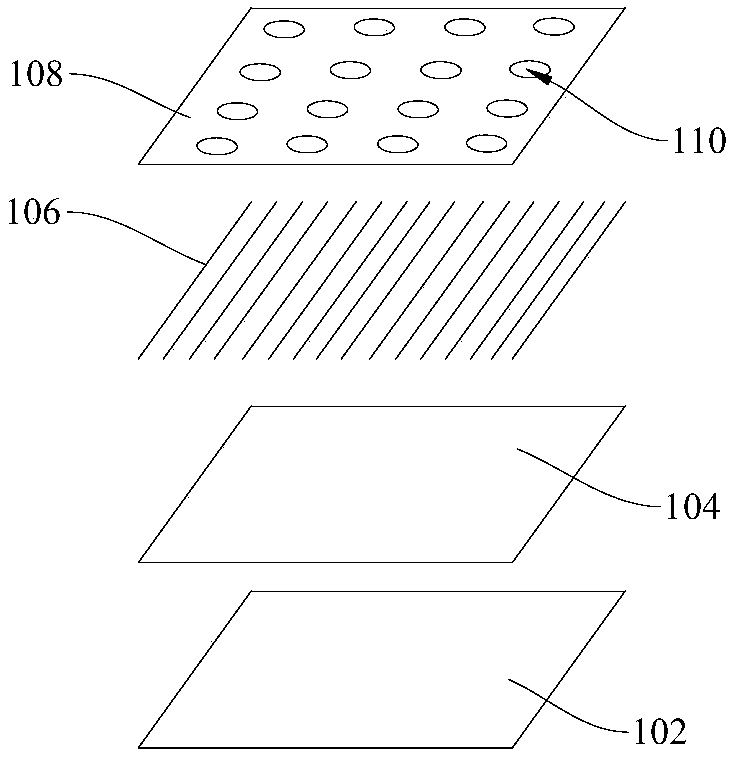
[0034] In this embodiment, the plasma generating assembly 100 includes a power source (not shown in the figure), and a first electrode 102 , an insulating medium 104 , a second electrode 106 , and an insulating layer 108 connected in sequence. The first electrode 102 and the second electrode 106 are respectively connected to the positive pole and the negative pole of the power supply, that is, the first electrode 102 is used as a high voltage electrode, and the second electrode 106 is used as a ground electrode. The first electrode 102 , the insulating medium 104 , the second electrode 106 , and the insulating layer 108 are tightly bonded in sequence.

[0035] Please refer to figure 2 , figure 2 Shown is a schematic diagram of...

Embodiment 2

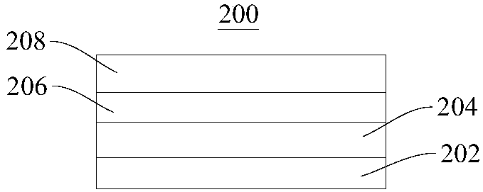
[0048] Please refer to image 3 , image 3 Shown is a schematic structural diagram of the plasma generating assembly 200 provided in this embodiment. This embodiment provides a plasma generating assembly 200, which is mainly used for generating surface glow plasma.

[0049] In this embodiment, the plasma generating assembly 200 includes a power source (not shown in the figure), and a first electrode 202 , an insulating medium 204 , a second electrode 206 , and an insulating layer 208 connected in sequence. The first electrode 202 and the second electrode 206 are respectively connected to the positive pole and the negative pole of the power supply, that is, the first electrode 202 is used as a high-voltage electrode, and the second electrode 206 is used as a ground electrode. The first electrode 202 , the insulating medium 204 , the second electrode 206 , and the insulating layer 208 are tightly bonded in sequence.

[0050] Please refer to Figure 4 , Figure 4 Shown is a ...


PUM

PropertyMeasurementUnit
thicknessaaaaaaaaaa
thicknessaaaaaaaaaa
thicknessaaaaaaaaaa

Abstract

The present invention provides a plasma generation module and an air cleaner, and relates to the technical field of plasma generation. The plasma generation module comprises a power supply and a firstelectrode, an insulation medium and a second electrode which are connected in order. The first electrode and the second electrode are respectively connected with a positive pole and a negative pole of the power supply. the thickness of the insulation medium is smaller than or equal to 100 micrometers, and the thickness of the second electrode is smaller than or equal to 30 micrometers. In a traditional method, in order to achieve glow discharge, a distance is arranged between a high-voltage electrode and a low-voltage electrode to allow discharge to be generated in an air gap, the plasma generated in this mode is poor in diffusion and is difficult to utilize. In the embodiment, the first electrode, the insulation medium and the second electrode are tightly connected in order, thickness ofmaterials is properly controlled to achieve generation of the plasma with surface glow and allow the generated plasma to be located at the periphery of the second electrode and even wrap the whole second electrode and perform diffusion towards two sides.

Description

technical field [0001] The invention relates to the technical field of plasma generation, in particular to a plasma generation component and an air purification device. Background technique [0002] The plasma generated by atmospheric pressure glow discharge (APGD) can be widely used in plasma chemical vapor deposition, plasma surface treatment technology and other fields due to its advantages of uniformity, low current density, and low discharge voltage. APGD also produces a wide variety of active particles such as oxygen atoms (O), hydroxyl (OH), nitric oxide (NO), hydrogen peroxide (H2O2), ozone (O3) and their excited state particles in the air. , environmental protection, nanotechnology and other application fields play a key role. [0003] The large area and relatively uniform glow discharge plasma layer generated on the surface can convert electrical energy into air kinetic energy without the need for mechanical moving parts, avoiding the complex structure of traditio...

Claims


Application Information

Patent Timeline
Patent Type & Authority Applications(China)
IPC IPC(8): H05H1/46A61L9/22
CPCH05H1/46A61L9/22
Inventor 刘文正赵潞翔
Owner BEIJING RUIYUDA TECH
Why Eureka
Try Eureka