Dry reaction accelerator with elevated circulating fluid mixing flow

An accelerator, dry technology, used in gas treatment, lighting and heating equipment, chemical instruments and methods, etc., can solve the problems of low desulfurization rate, short waste gas residence time, complex structure desulfurization rate, etc., and achieve the effect of effective reaction

Active Publication Date: 2021-03-09
SN股份有限公司
View PDF8 Cites 0 Cited by
  • Summary
  • Abstract
  • Description
  • Claims
  • Application Information

AI Technical Summary

Problems solved by technology

[0008] However, in the conventional reactor, the residence time of exhaust gas in the fluidized part is relatively short, and the desulfurization rate is relatively low, and the structure of the device is complicated for increasing the desulfurization rate

Method used


Image

  • Dry reaction accelerator with elevated circulating fluid mixing flow
  • Dry reaction accelerator with elevated circulating fluid mixing flow
  • Dry reaction accelerator with elevated circulating fluid mixing flow

Examples


Embodiment Construction

[0034] Hereinafter, exemplary embodiments of the present invention will be described in detail with reference to the accompanying drawings.

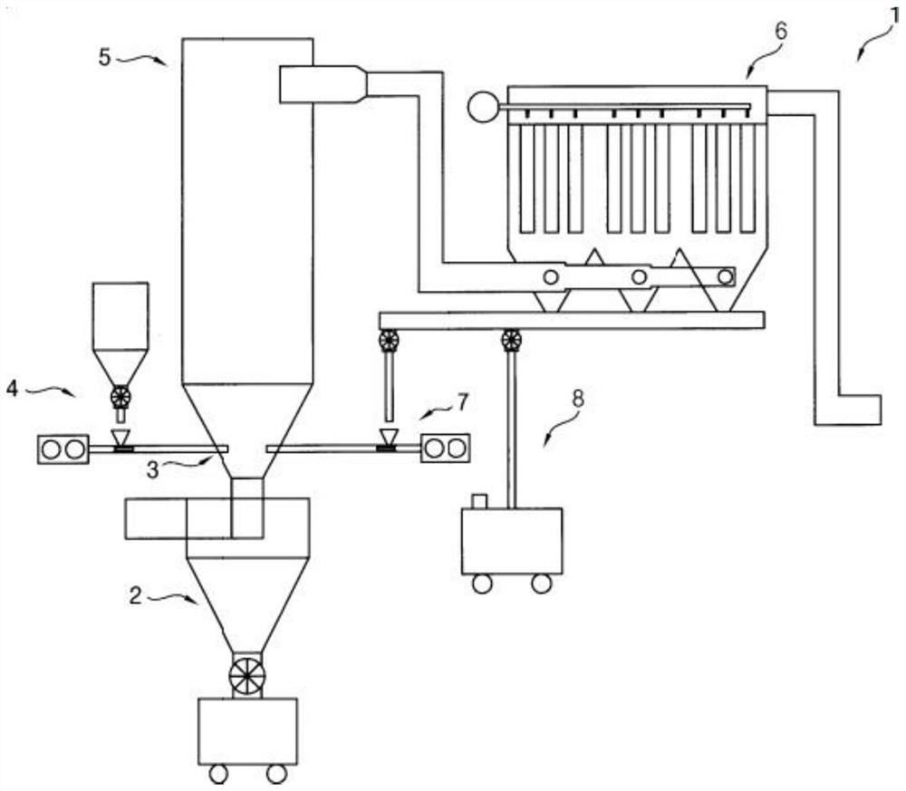
[0035] figure 1 is a schematic diagram showing a conventional dry reaction accelerator.

[0036] see figure 1 , Dry reaction accelerator 1 (Korean Patent No. 10-1617759) includes a cyclone chamber 2, an accelerating part 3, a reactant provider 4, a reaction chamber 5, a filter collection part 6, a reactant re-provider 7 and a particle outlet 8.

[0037] More specifically, the cyclone chamber 2 circulates the incoming exhaust gas to remove particulate matter contained in the exhaust gas. The acceleration part 3 is connected to the upper part of the cyclone chamber 2 , and reactants flow into the acceleration part 3 . The accelerating part 3 accelerates the circulation and rising speed of the exhaust gas to more evenly distribute and diffuse the reactant and the exhaust gas.

[0038] The reactant supplier 4 supplies a reactant to the a...


PUM


Abstract

A dry reaction accelerator comprises a reaction unit, wherein the reaction unit comprises a cyclone chamber, an acceleration diffuser and a reaction chamber. The cyclone chamber rotates the flue gas containing the particulate matter introduced into the inlet portion to remove the particulate matter. The accelerating diffuser is connected to an upper portion of the cyclone chamber to introduce a reactant, accelerating the rotational flow and the ascending velocity of the exhaust gas, thereby dispersing and diffusing the reactant and the exhaust gas. The reaction chamber is connected to the upper portion of the acceleration diffuser, and the reactant and the exhaust gas are circulated in the reaction chamber and upwardly rotated and react with each other, and are discharged to the outlet portion. A baffle is disposed in the upper side of the reaction chamber to induce recirculation of the reactant and the exhaust gas, thereby reducing the pressure of the reaction chamber.

Description

technical field [0001] The present invention relates to a dry reaction accelerator, and more particularly, the present invention relates to a dry reaction accelerator with an elevated circulating fluid mixed flow for removing toxic gas (HCL , SO 2 , HF, etc.), and improve the removal rate of toxic gases and the reaction rate of powder absorbents. Background technique [0002] Desulfurization methods for removing sulfur oxides contained in exhaust gas from combustion or waste incineration include dry desulfurization, wet desulfurization, and semi-dry desulfurization. [0003] In dry desulfurization, the exhaust gas is passed through a bed of powdered or granular catalyst. Water is unnecessary, and after removal of sulfur dioxide, the temperature of the exhaust gas remains uniform, therefore, no reheating is required in the dry desulfurization method. However, the reaction rate is slow, requiring relatively large-sized devices, and the removal rate of sulfur dioxide is rela...

Claims


Application Information

Patent Timeline
Patent Type & Authority Patents(China)
IPC IPC(8): B01D53/50B01D53/83
CPCB01D53/508B01D2251/404B01D2251/604B01D2258/0283F23J15/003F23J15/025F23J15/027F23J2217/10F23J2217/40
Inventor 韩邦熙韩縡沅朴永玉金光得纳伊姆·哈索里全星玟李江山李在朗
Owner SN股份有限公司
Why Eureka
Try Eureka