

Method for obtaining high-density unequal height crystal microneedle array
A microneedle array, high-density technology, applied in the direction of microneedles, instruments introduced into the body, needles, etc., can solve the problems of cumbersome process and too many steps, and achieve the effect of high etching precision, accurate shape and avoiding errors
- Summary
- Abstract
- Description
- Claims
- Application Information
AI Technical Summary
Problems solved by technology
Method used
Image

Examples
Embodiment 1
[0046] 1) Obtain the full space rate distribution of quartz etching:
[0047] Such as Figure 5 with Image 6 As shown, a three-coordinate measuring machine is used to measure the data points on the surface of the quartz ball before and after the etching to obtain the anisotropic rate of quartz wet etching in different directions, thereby obtaining the full space rate of the quartz anisotropic etching.
[0048] 2) Establish the etching model of the needle-shaped boss:
[0049] The etching model of the needle-shaped boss is divided into two parts: the first part is the mask drilling model, and the second part is the free etching model after the mask comes off.
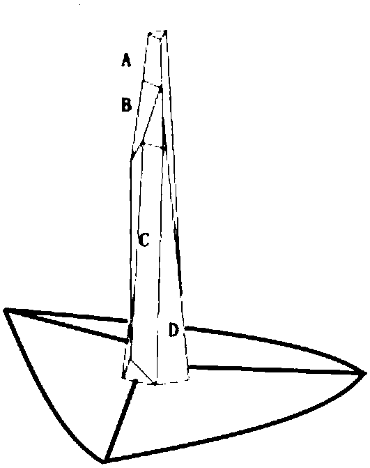
[0050] Such as image 3 As shown, a needle-like boss is observed separately. For the needle-like structure in the figure, when viewed from one side, there are four main faces: A, B, C, and D. Since the Z-cut quartz wafer has a three-symmetric structure, these surfaces will inevitably be repeated during the process of rotating t...
Embodiment 2
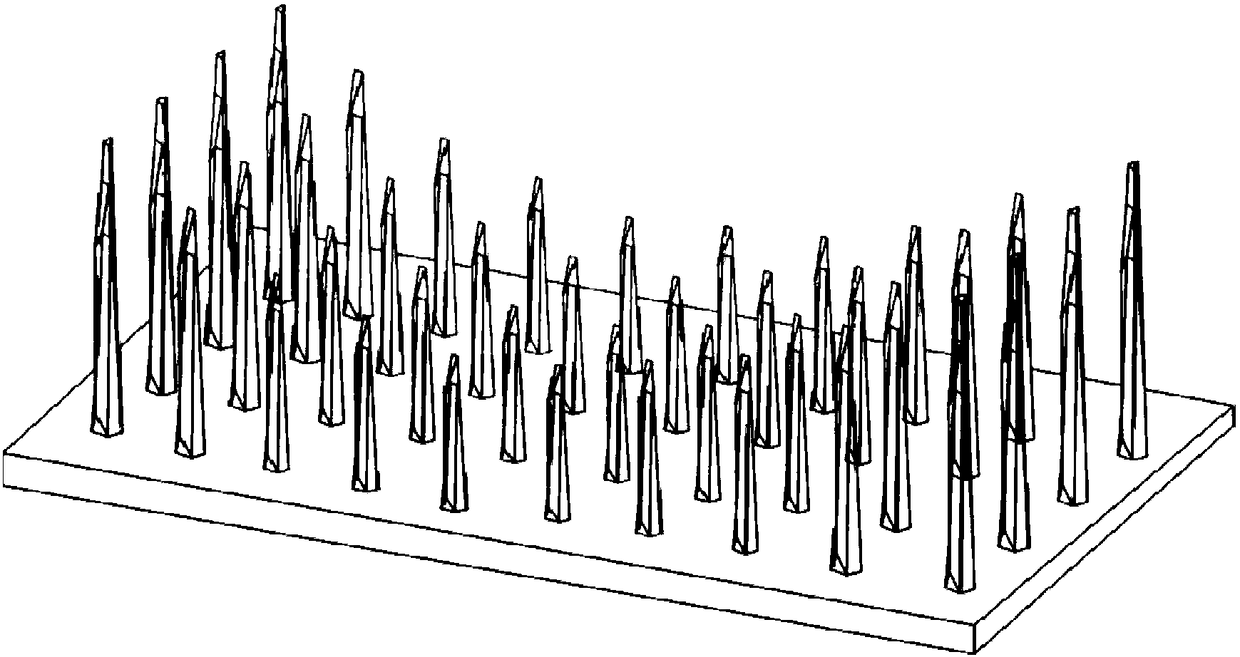
[0086] Such as figure 1 with Figure 17 As shown, the microneedle array is composed of multiple linear arrays with linear and equidistant tops arranged in parallel. Figure 16 A schematic diagram of the etching of a cluster of linear arrays with linear and equidistant tops is given. When the mask shape is circular, step 3) the mask radius R in Step5 i Calculated as follows:
[0087]
[0088] Where i is the i-th needle boss from high to low in the same cluster of linear arrays, θ is the angle between the diagonal line and the horizontal line formed by the top of the linear array, n is the number of needle bosses in a linear array, k s Is the fastest rate of mask erosion, k h Is the rate of change of boss height during free etching, R 1 Is the radius of the initial needle-shaped boss covering the mask, and D is the distance between the axis of two adjacent needle-shaped bosses in the same cluster array.
[0089] Considering its limit, when the needle column disappears, only the base is...
Embodiment 3
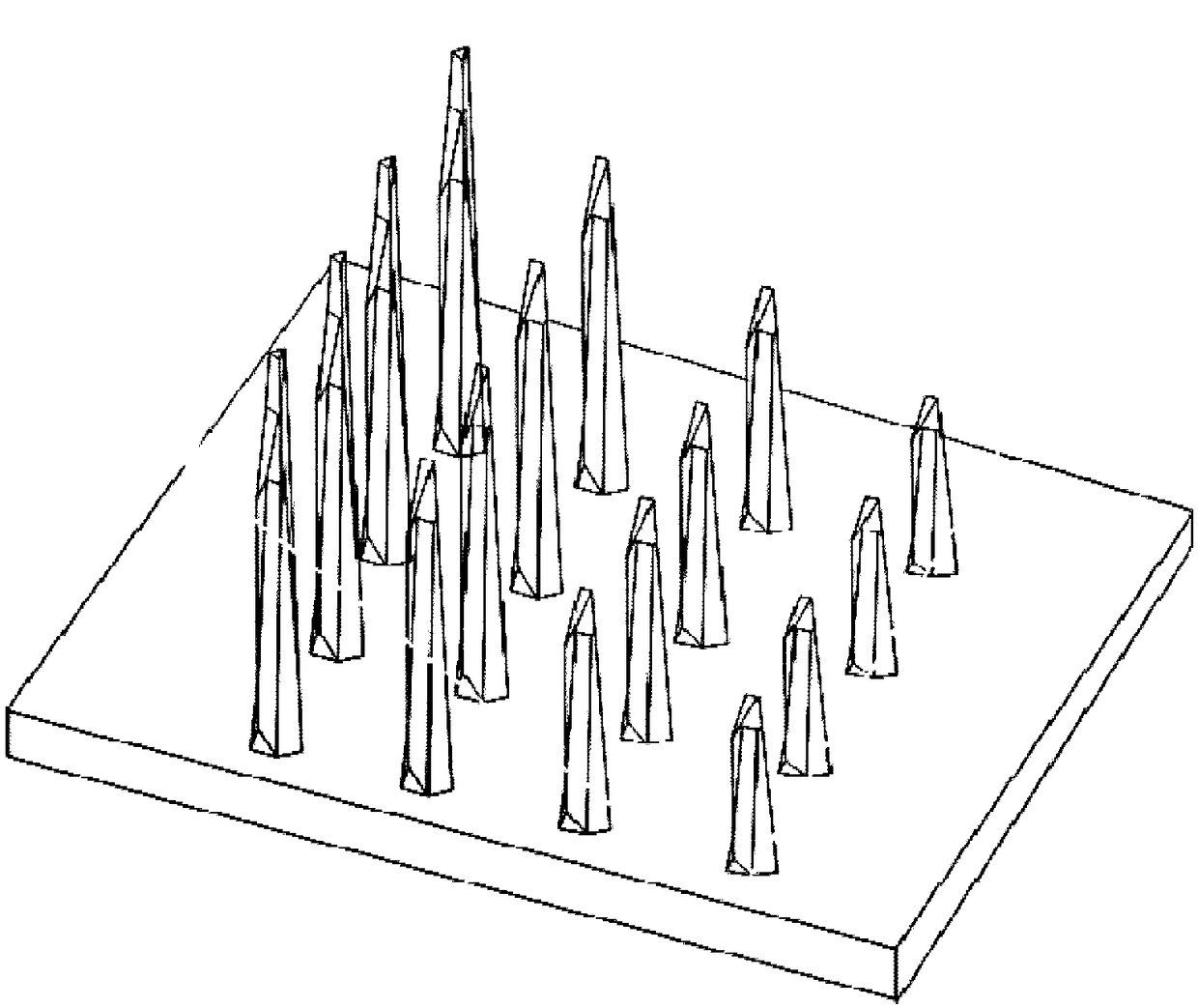
[0099] Such as figure 2 with Figure 18 As shown, the microneedle array is composed of a plurality of curved arrays with symmetrical parabolic tops and equidistantly arranged in parallel, and the top parabolic translation surface, Figure 14 The etching schematic diagram of the half parabolic arrangement is given. When the mask shape is circular, step 3) Mask radius R i Calculated as follows:
[0100]
[0101] Where i represents the i-th needle boss from high to low in the same cluster of linear array, n is the number of needle bosses in the same cluster of array, k s Is the fastest rate of mask erosion, k h Is the rate of change of boss height during free etching, R 1 Is the radius of the initial needle boss covering the mask, D is the distance between the axis of two adjacent needle bosses in the same cluster array, and ɑ is the quadratic coefficient of the quadratic function corresponding to the parabola. Mirror the mask size to obtain a symmetrical parabolic and equidistant ar...
PUM
 Abstract
Description
Claims
Application Information