
Polygonal drum skew rolling ball-milling steel ball quenching unit

A quenching device, polygonal technology, applied in the direction of quenching device, furnace, furnace type, etc., can solve the problems of small quenching area, chaotic steel ball movement, complex and huge, etc., achieve simple processing and manufacturing assembly process, reduce manufacturing and assembly cost, and economical low cost effect

Pending Publication Date: 2018-07-27
UNIV OF SCI & TECH BEIJING +1
View PDF1 Cites 8 Cited by
  • Summary
  • Abstract
  • Description
  • Claims
  • Application Information

AI Technical Summary

Problems solved by technology

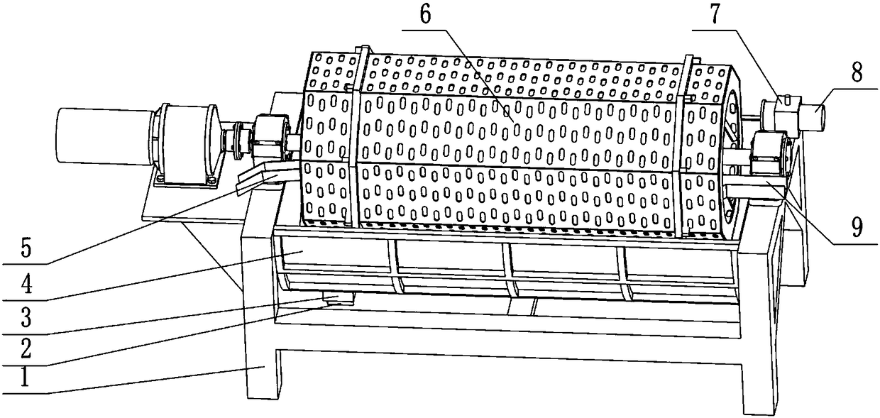
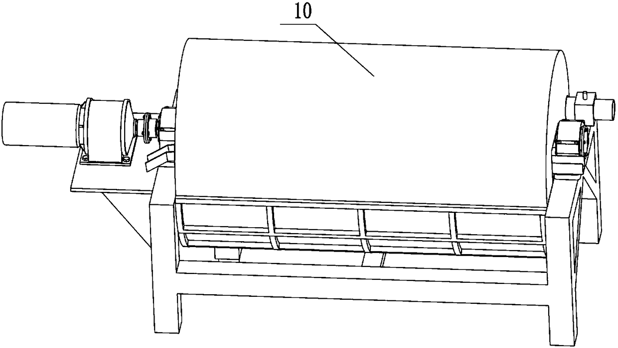
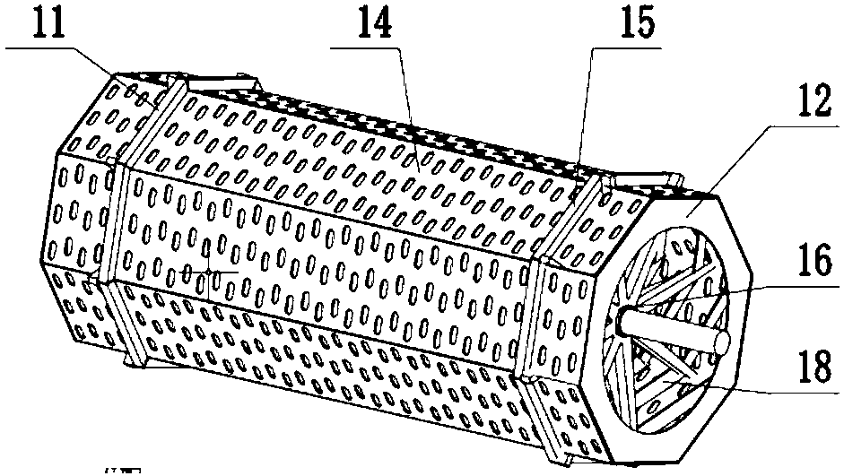
[0004] The present invention provides a polygonal drum-type oblique rolling ball mill steel ball quenching device, aiming at the existing drum-type quenching equipment, which is complicated and bulky, high in manufacturing and assembly costs, and difficult to manufacture the equipment structure, and the steel ball stays at the bottom of the drum so that the quenching area is small , easy to accumulate, high local temperature, chaotic steel ball movement so that the quenching time is not accurate, steel balls do not roll so that the quenching effect is not good, etc. The device is improved to a polygonal drum type, and the steel balls are divided into channels in the quenching device in an orderly manner. After lifting, the spiral rolls to complete the quenching. It has the advantages of simple equipment structure, low manufacturing and assembly costs, large quenching area of ​​steel balls, no accumulation of steel balls, orderly movement of steel balls, and accurate quenching time.

Method used


Image

  • Polygonal drum skew rolling ball-milling steel ball quenching unit
  • Polygonal drum skew rolling ball-milling steel ball quenching unit
  • Polygonal drum skew rolling ball-milling steel ball quenching unit

Examples


Embodiment Construction

[0029] In order to make the object, technical solution and advantages of the present invention clearer, the present invention will be further described in detail below in conjunction with the accompanying drawings and embodiments. It should be understood that the specific embodiments described here are only used to explain the present invention, not to limit the present invention.

[0030] On the contrary, the invention covers any alternatives, modifications, equivalent methods and schemes within the spirit and scope of the invention as defined by the claims. Further, in order to make the public have a better understanding of the present invention, some specific details are described in detail in the detailed description of the present invention below. The present invention can be fully understood by those skilled in the art without the description of these detailed parts.

[0031] The present invention will be further described below in conjunction with the accompanying draw...


PUM


Abstract

The invention provides a polygonal drum skew rolling ball-milling steel ball quenching unit which is used for conducting quenching heat treatment on skew rolling ball-milling steel balls with the diameter phi of 20-80 mm to quickly cool the skew rolling ball-milling steel balls from 800 DEG C-900 DEG C to 100 DEG C-300 DEG C. A quenching drum of the quenching unit is a polygonal drum composed of aplurality of drum flat plates. The inner sides of the drum flat plates are provided with drum partition boards and steel ball lifting plates. The drum partition boards are arranged obliquely. Spiralgrooves are formed between the drum partition boards. The steel balls go into the quenching unit through a ball inlet channel are lifted up by polygonal interior angles through subchannels of the polygonal drum in order and then are subjected to rolling quenching in the spiral grooves. The steel balls at the tail ends of the spiral grooves are lifted up to a certain height by the steel ball lifting plates and then freely fall to a ball outlet channel to be discharged. The drum flat plates are provided with kidney-shaped through holes, the kidney-shaped through holes are used for allowing a quenching medium inside and outside the drum to flow to achieve internal and external heat exchange of the drum and finally complete quenching. The polygonal drum skew rolling ball-milling steel ball quenching unit achieves safe, economical and high-quality quenching of the skew rolling ball-milling steel balls.

Description

technical field [0001] The invention belongs to the technical field of metal plastic forming technology and equipment, and in particular relates to a polygonal drum-type oblique rolling mill steel ball quenching device. technical background [0002] In ore grinding and crushing operations, ball milling steel balls are used as the grinding medium of ball mills and semi-autogenous mills, and there are effects of impact, extrusion, and grinding between themselves and the ore, causing ball milling steel balls to become industrially easy. Consumables. The annual consumption of steel balls in the world is 5-8 million tons, and the consumption of steel balls in China is 3-4 million tons, which is a big consumption country of steel balls. [0003] The oblique rolling milling steel ball process is widely used because it can produce 30-180 steel balls per minute, the material utilization rate is as high as 98%, the dimensional accuracy is high, the working conditions are good, the pr...

Claims


Application Information

Patent Timeline
IPC IPC(8): C21D9/36C21D1/63
CPCC21D1/63C21D9/0062C21D9/36Y02P10/20
Inventor 王宝雨林龙飞刘晋平张弢孙歌
Owner UNIV OF SCI & TECH BEIJING
Learn More