Method for mounting large-span arch bridge tie bars

A technology for long-span arch bridges and tie rods, which is applied to arch bridges, erecting/assembling bridges, bridges, etc., can solve the problems of long-time occupation of cable cranes, many manual aerial operations, and difficult communication, and reduce aerial operations and manual operations. , to meet the effect of rapid construction, convenient construction and easy operation

Inactive Publication Date: 2018-07-27
CHINA RAILWAY MAJOR BRIDGE ENG GRP CO LTD
View PDF5 Cites 1 Cited by
  • Summary
  • Abstract
  • Description
  • Claims
  • Application Information

AI Technical Summary

Problems solved by technology

[0003] The gantry crane is only suitable for the installation of small-span arch bridge tie rods, and the assembly and installation of the gantry crane is time-consuming and laborious. The foundation construction is difficult, and it also occupies the waterway. It is difficult to communicate with relevant departments, which has a certain impact on the construction period.
[0004] When setting the load-bearing cables and installing the tie bars, a lot of materials are required, and the construction process is complicated, which has a great impact on the construction period
[0005] When using the cable crane to install the tie rod, there are many artificial high-altitude operations, the risk factor is large, and the cable crane takes a long time, which has a great impact on the construction period

Method used


Image

  • Method for mounting large-span arch bridge tie bars
  • Method for mounting large-span arch bridge tie bars
  • Method for mounting large-span arch bridge tie bars

Examples


Embodiment Construction

[0034] The present invention will be described in further detail below in conjunction with the accompanying drawings.

[0035] The invention provides a method for installing tie rods of a long-span arch bridge, the method comprising the following steps:

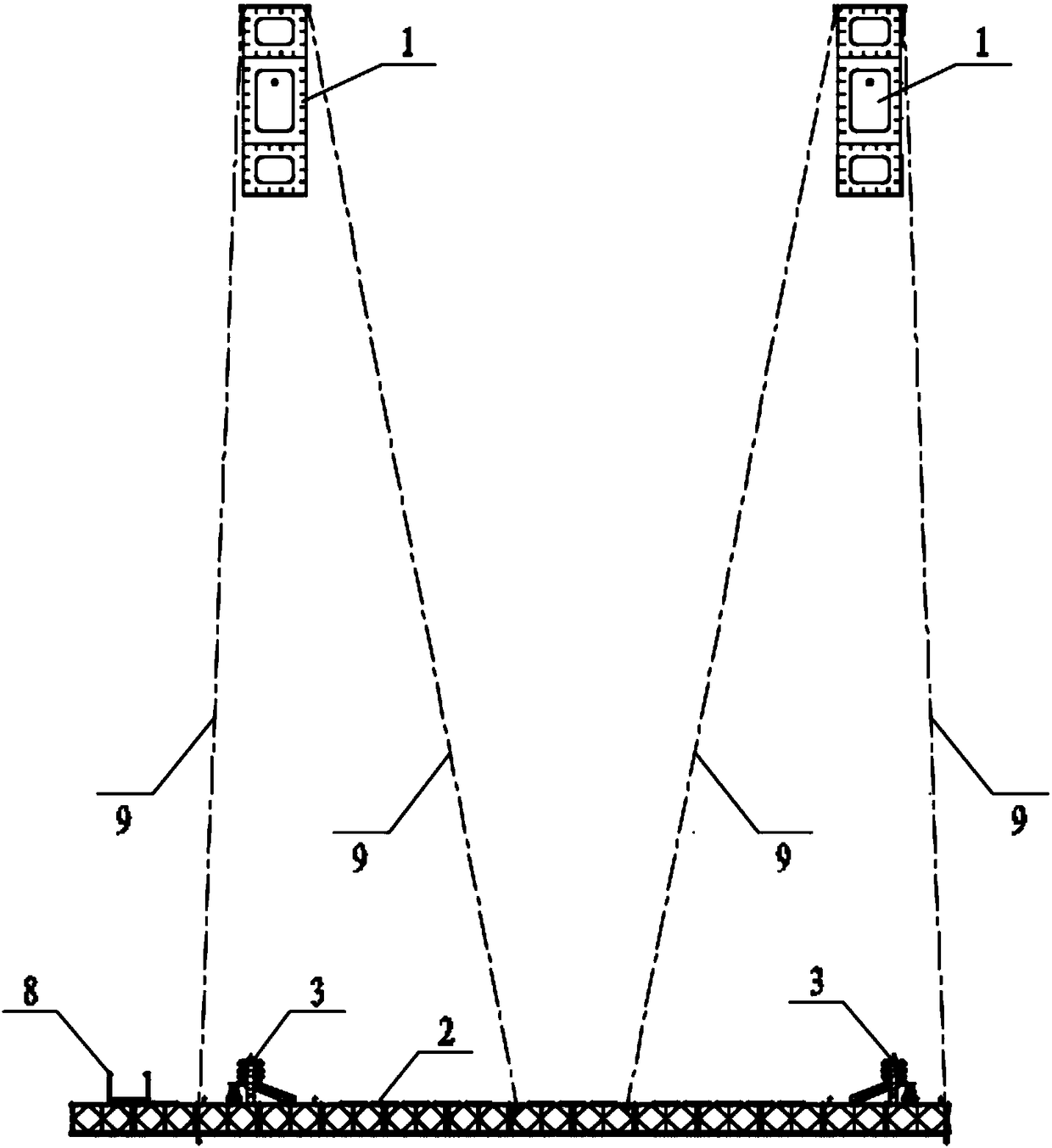
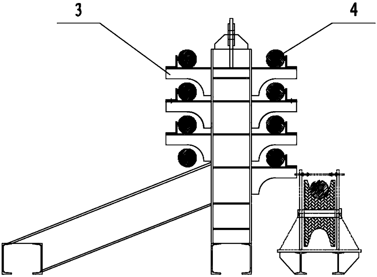
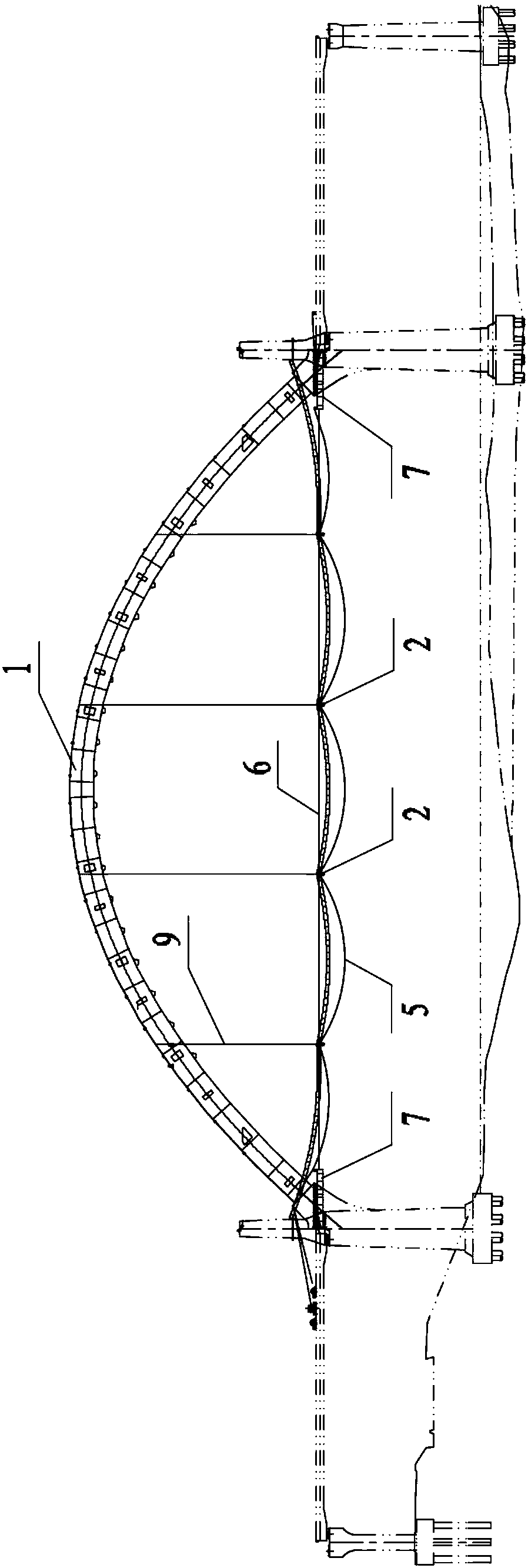
[0036] S1. See Figure 1 to Figure 3 As shown, a plurality of brackets 2 are suspended at intervals on the arch rib 1, and at least one support frame 3 is arranged on each bracket 2, and a plurality of spaces for receiving tie rods 4 are provided on the support frame 3, and on both sides of the arch bridge Windlass and traction rope 5 are installed at the end;

[0037] Specifically, each support 2 is suspended on the ring of the arch rib 1 through a wire rope 9, and the support 2 in the present invention is a Bailey beam support. In addition, a reciprocating traction system can be formed after installing hoists and traction cables 5 at both ends of the arch bridge.

[0038] The present invention also utilizes the connectin...


PUM


Abstract

The invention discloses a method for mounting large-span arch bridge tie bars and relates to the field of bridge engineering construction. The method includes following steps: S1, hanging multiple supports on arch ribs at intervals, arranging at least one supporting frame on each support, arranging multiple spaces for storing the tie bars on the supporting frames, and mounting a winch and a traction rope at two ends of an arch bridge; S2, connecting the front end of one tie bar with the traction rope, and starting the winch to enable the tie bar to sequentially pass all supports from one sideof the arch bridge; S3, allowing the winch to continue working to enable the tie bar to penetrate a pipeline positioned on the other side of the arch bridge, and putting the tie bar on the supportingframes; S4, repeating the steps S2-S3 to put the rest tie bars onto the supporting frames; S5, penetrating two ends of all tie bars into a tensioning device, and utilizing the tensioning device to synchronously tension all tie bars to finish. The method is free of channel occupation, short in construction period and needless of a cable crane for aerial operation.

Description

technical field [0001] The invention relates to the field of bridge engineering construction, in particular to a method for installing tie bars of a long-span arch bridge. Background technique [0002] In the existing arch bridge tie bar construction, the most commonly used method is to set the gantry crane and load-bearing cables, or to use the cable crane to assist in its installation. [0003] The gantry crane is only suitable for the installation of small-span arch bridge tie bars, and the assembly and installation of the gantry crane is time-consuming and laborious. The foundation construction is difficult, and it also occupies the waterway. It is difficult to communicate with relevant departments, which has a certain impact on the construction period. [0004] When setting the load-bearing cables and installing the tie rods, a lot of materials are required, and the construction process is complicated, which has a great impact on the construction period. [0005] When ...

Claims


Application Information

Patent Timeline
IPC IPC(8): E01D21/00E01D4/00
CPCE01D21/00E01D4/00
Inventor 杜凤张小川李方峰毛玮琦涂满明李艳哲谢守杰马涛刘翠云韩井东代皓岳万友赖维斌邹冠黄根
Owner CHINA RAILWAY MAJOR BRIDGE ENG GRP CO LTD
Why Eureka
Try Eureka