Supercharge Your Innovation With Domain-Expert AI Agents!

Horizontal well structure for heap precipitation of garbage landfill site and construction method

A technology for a landfill site and a construction method, which is applied in the field of leachate water level control in a landfill site, can solve problems such as difficulty in meeting the water level control requirements of a heap body, achieve good corrosion resistance and deformation resistance, improve work performance, and ensure Feasibility effect

Inactive Publication Date: 2018-07-27
ZHEJIANG UNIV +2
View PDF1 Cites 3 Cited by
  • Summary
  • Abstract
  • Description
  • Claims
  • Application Information

AI Technical Summary

Problems solved by technology

[0004] In order to overcome the problem that it is difficult for a single pumping shaft to meet the water level control requirements of the heap, the present invention provides a new type of dewatering measure for landfills—the structure and construction method of a horizontal well. With the advantages of large area and high working efficiency, the joint use of horizontal wells and vertical wells can realize three-dimensional drainage, which can better meet the requirements of water level control of the pile

Method used


Image

  • Horizontal well structure for heap precipitation of garbage landfill site and construction method
  • Horizontal well structure for heap precipitation of garbage landfill site and construction method
  • Horizontal well structure for heap precipitation of garbage landfill site and construction method

Examples


Embodiment Construction

[0031] The present invention will be described in further detail below in conjunction with the accompanying drawings and specific embodiments.

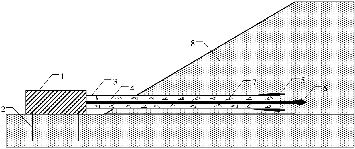
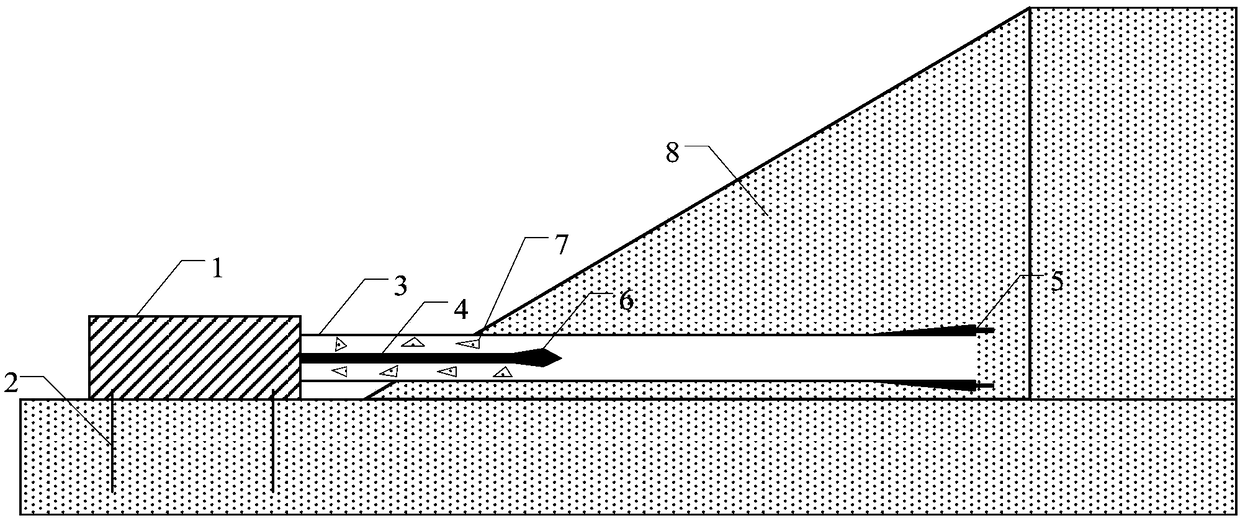
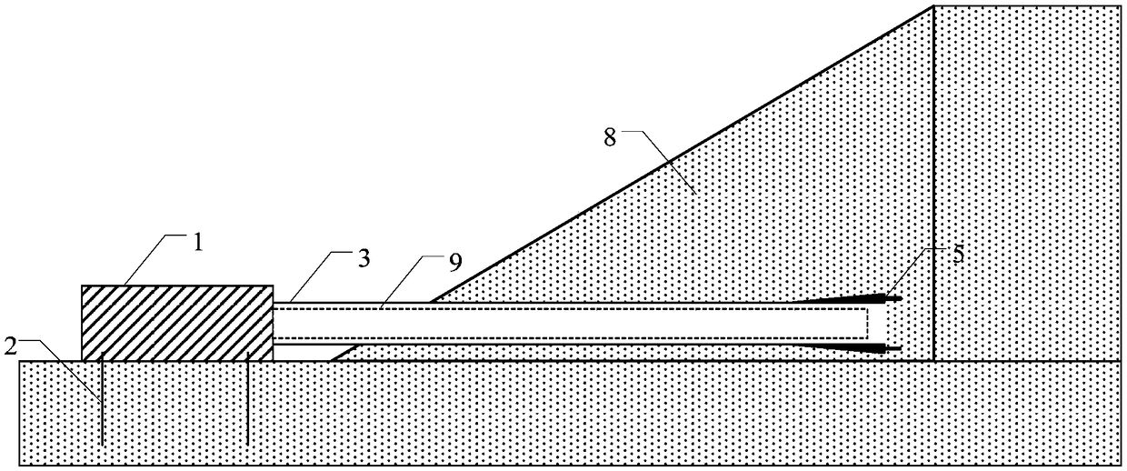
[0032] The well pipe 9 of the horizontal well of the present invention has a diameter of 133mm and a wall thickness of 6mm; the front section is a galvanized steel pipe without holes, and is used as a negative pressure suction sealing section, and the length is 12m; the middle section has holes in the upper semicircle and no holes in the lower semicircle The galvanized steel pipe, in which the upper semicircle has holes, the hole diameter is 12mm, and the hole rate is 6%. It is used as the leachate inflow surface, and the bottom semicircle has no holes, which is used as the leachate flow channel, and the length is 42m; galvanized steel pipe, the end is sealed with a plug to prevent garbage from entering the well pipe, the length is 3m; the length of a single well pipe is 3m, in order to ensure that the upper semicircle of each well pip...


PUM

PropertyMeasurementUnit
Outer diameteraaaaaaaaaa
Wall thicknessaaaaaaaaaa
Apertureaaaaaaaaaa

Abstract

The invention discloses a horizontal well structure for heap precipitation of a garbage landfill site and a construction method. A galvanized steel pipe without holes is arranged on the front sectionof a well pipe to be used as a negative pressure air exhaust sealing section. A galvanized steel pipe with the upper half circle provided with holes and the lower half circle not provided with holes is arranged on the middle section of the well pipe, wherein the upper half circle is used as an inflow surface of leachate, and the lower half circle is used as a flow channel of the leachate. A galvanized steel pipe without holes is arranged on the rear section of the well pipe, and the tail end of the galvanized steel pipe is blocked by a plug. The well pipe has a rising angle of 3%-15%. The construction method of the horizontal well structure comprises the following steps that a guide drill pipe is firstly used for drilling forward according to the specified rising angle, and a casing pipe synchronously follows to the designed length to form a well bore by adopting a pipe-following positive circulation drilling process to ensure the space for installing the well pipe; then the guide drill pipe is withdrawn and the well pipe is extended section by section into the casing pipe; and finally, the casing pipe is withdrawn so that the well pipe can be implanted into a heap to realize drainage. The drainage of the horizontal well is performed by adopting a self-flow method, and high pressure backwash technology can be used for removing silt in case of subsequent long-term operation.

Description

technical field [0001] The invention relates to the field of leachate water level control in landfill sites, in particular to a horizontal well structure and construction method for dewatering piles in landfill sites. Background technique [0002] In my country's current urban domestic garbage sanitary landfills, the daily landfill volume of garbage and the large leachate output, the long-term drainage of leachate is not smooth, and the leachate that cannot be effectively guided is deposited in the landfill, resulting in the level of leachate in the garbage dump. Generally Yonggao. When the leachate water level in the landfill is too high, part of the leachate leaks laterally along the weak parts of the side cover of the garbage dump, which seriously pollutes the surrounding environment and causes various forms of landfill slope instability. Excessive leachate water level will also inhibit the generation, collection and utilization of methane gas, and it is easy to form a hi...

Claims


Application Information

Patent Timeline
IPC IPC(8): E02D19/10E02D3/10
CPCE02D3/10E02D19/10E02D2250/0076
Inventor 胡杰兰吉武张海华詹良通柯瀚徐晓兵黄耆馨赵军夏睿祺孙顺杰唐素琴
Owner ZHEJIANG UNIV
Features
  • R&D
  • Intellectual Property
  • Life Sciences
  • Materials
  • Tech Scout
  • Unparalleled Data Quality
  • Higher Quality Content
  • 60% Fewer Hallucinations
Learn More