

Device and method for measuring light polarization in nanofiber
A nano-fiber and light polarization technology, applied in the field of nano-fiber polarization measurement and control, can solve the problems of poor signal-to-noise ratio and low control accuracy.
- Summary
- Abstract
- Description
- Claims
- Application Information
AI Technical Summary
Problems solved by technology
Method used
Image

Examples
Embodiment
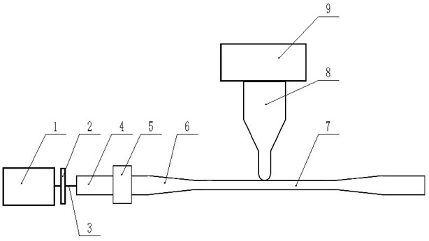
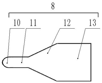
[0033] Such as figure 1 , figure 2 As shown, a device for measuring light polarization in a nanofiber includes a test laser 1, a half-wave plate 2, a fiber polarization controller 5, a fiber probe 8 and a photodetector 9, and the test laser 1 outputs laser light with a wavelength of 852nm in sequence Enter the nano-fiber 7 through the half-wave plate 2, the first common fiber 4, the fiber polarization controller 5 and the first tapered fiber 6, the fiber probe 8 is connected to the photodetector 9 through the second common fiber 13, and the fiber probe 8 The tip 10 is in contact with the surface of the nano-fiber 7, the evanescent field laser transmitted by the surface of the nano-fiber 7 is coupled into the fiber probe 8, and the ordinary fiber 4, the first tapered fiber 6 and the nano-fiber 7 are integrally formed.
[0034] The tip 10 of the fiber probe 8 is hemispherical, and a section of cylindrical optical fiber 11 is connected to the rear end of the tip 10 , and a seco...
PUM
| Property | Measurement | Unit |
|---|---|---|
| diameter | aaaaa | aaaaa |
Abstract
Description
Claims
Application Information