Dephasing self-coupling zigzag transformer

A zigzagging transformer and transformer technology, applied in the field of transformers, can solve the problems of broken lines, increased transformer loss, large transformer zero-sequence current, etc., and achieve the effects of small no-load current, small no-load loss, and small impedance drop

Inactive Publication Date: 2018-07-27
JIANGSU LIYANG ELECTRIC MANFUACTURING CO LTD
View PDF6 Cites 1 Cited by
  • Summary
  • Abstract
  • Description
  • Claims
  • Application Information

AI Technical Summary

Problems solved by technology

[0006] During the operation of the phase-shifting auto-coupling transformer in the prior art, a certain magnitude of zero-sequence current will pass through, which will cause the following effects:
[0007] First, the impact on distribution transformers
[0008] (1) The unbalanced three-phase load will increase the loss of the transformer;
[0009] (2) Unbalanced three-phase load may cause serious consequences of burning the transformer;
[0010] (3) The unbalanced operation of the three-phase load will cause the zero-sequence current of the transformer to be too large, and the temperature rise of local metal parts will increase;
[0011] Second, the impact on high-voltage lines
[0012] (1) Increase the loss of high-voltage lines;
[0013] (2) Increase the number of high-voltage line trips and reduce the service life of switchgear;
[0014] 3. Impact on power distribution panel and low-voltage lines
[0015] (1) Unbalanced three-phase load will increase line loss;
[0016] (2) The unbalanced three-phase load may cause serious consequences of burning the line and burning the switchgear;
[0017] 4. Negative impact on power supply enterprises and users

Method used


Image

  • Dephasing self-coupling zigzag transformer
  • Dephasing self-coupling zigzag transformer
  • Dephasing self-coupling zigzag transformer

Examples


Embodiment Construction

[0041] The present invention will be described in detail below with reference to the accompanying drawings and in combination with embodiments.

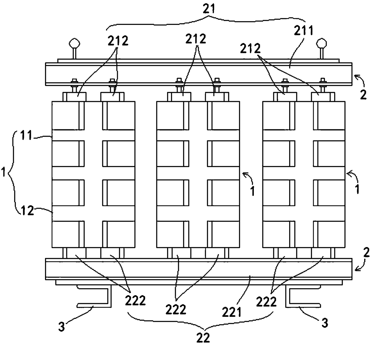
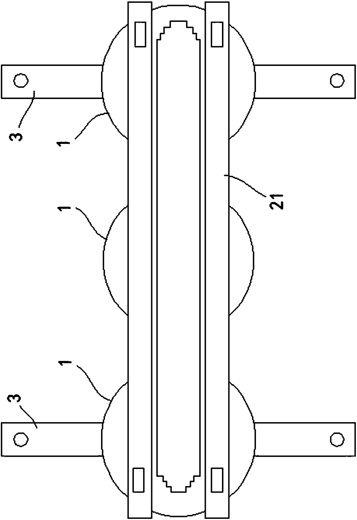
[0042] refer to figure 1 , figure 2 As shown, a phase-shifting auto-coupling transformer is connected with a transformer load and an arc-suppression coil load, including a three-phase high-voltage winding 1, and each phase coil of the high-voltage winding 1 is composed of an upper coil 11 and a lower coil with the same number of turns. Composed of coils 12, the upper coil 11 is set on the upper iron core 21 of the three-phase iron core 2, the lower coil 12 is set on the lower iron core 22 of the three-phase iron core 2, and the upper coil 11 is The main winding with voltage regulating tap, the lower coil 12 is a phase shifting winding with a phase shifting effect, and the phase shifting winding and the voltage regulating winding have a phase relationship of 60° on each phase.

[0043] Each phase coil of the high-voltage winding 1 ...


PUM


Abstract

The invention discloses a dephasing self-coupling zigzag transformer. The dephasing self-coupling zigzag transformer is connected with a transformer load and an arc-suppression-coil load. The dephasing self-coupling zigzag transformer comprises a three-phase high-voltage winding. Each phase of coil of the high-voltage winding comprises an upper coil and a lower coil. The upper coil and the lower coil have same number of turns. The upper coil sleeves an upper iron core of a three-phase iron core. The lower coil sleeves a lower iron core of the three-phase iron core. The upper coil is a main winding with a voltage-adjusting tap. The lower coil is a dephasing winding with a dephasing effect. The dephasing winding and the voltage-adjusting winding have a 60-degree phase relation on each phase.When zero sequence currents with a certain magnitude pass through the transformer, currents of the two single windings on a same steel iron core column are different in direction but same in magnitude, so that magnetic potentials generated by the zero sequence currents are opposite to be offset, and the zero-sequence impedance is low.

Description

technical field [0001] The invention relates to the field of transformers, in particular to a phase-shifting auto-coupling meander transformer. Background technique [0002] At present, with the diversification process of the rectification system, the rectification transformer, as the power supply part of the rectification system, also presents diversified characteristics. Since the rectifier winding current is non-sinusoidal and contains many high-order harmonics, in order to reduce the harmonic pollution to the grid and improve the power factor, the pulse number of the rectifier must be increased, which can be solved by phase shifting. The purpose of phase shifting is to make a phase shift between the voltages of the same-named terminal lines of the secondary winding of the rectifier transformer. [0003] The phase-shifting method is to use two windings connected by quantity and angle on the secondary side, which can double the pulse number of the rectifier electric furna...

Claims


Application Information

Patent Timeline
Patent Type & Authority Applications(China)
IPC IPC(8): H01F29/02H01F27/30H01F27/32H01F27/29H01F27/24
Inventor 朱铭彭飞
Owner JIANGSU LIYANG ELECTRIC MANFUACTURING CO LTD
Why Eureka
Try Eureka