Link oscillation test method, device and system

A technology of a testing device and a testing method, applied in the field of communications, can solve the problems of inability to accurately test the effectiveness of physical link oscillations, and achieve the effects of improving robustness and stability, and saving time for adjusting optical attenuation.

Active Publication Date: 2018-07-27
ZTE CORP
View PDF9 Cites 3 Cited by
  • Summary
  • Abstract
  • Description
  • Claims
  • Application Information

AI Technical Summary

Problems solved by technology

[0007] The technical problem to be solved by the present invention is to provide a link vibration testing method, device ...

Method used


Image

  • Link oscillation test method, device and system
  • Link oscillation test method, device and system
  • Link oscillation test method, device and system

Examples


Embodiment Construction

[0033] The present invention will be described in detail below in conjunction with the accompanying drawings. It should be understood that the specific embodiments described here are only used to explain the present invention, not to limit the present invention.

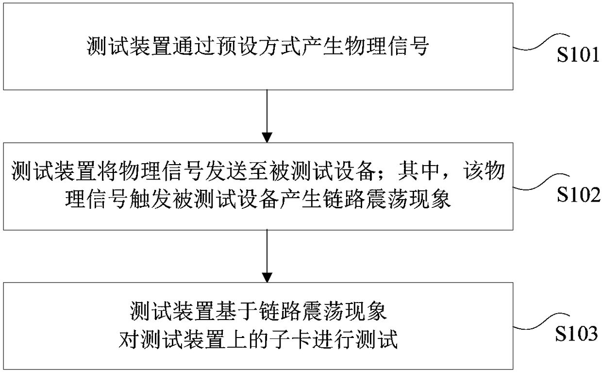
[0034] An embodiment of the present invention provides a link oscillation test method, figure 1 is a flow chart of a link oscillation testing method according to an embodiment of the present invention, such as figure 1 As shown, the method includes the following steps (step S101-step S103):

[0035] Step S101, the test device generates a physical signal in a preset manner;

[0036] Step S102, the test device sends a physical signal to the device under test; wherein, the physical signal triggers the device under test to generate a link oscillation phenomenon;

[0037] In step S103, the test device tests the daughter card on the test device based on the link oscillation phenomenon.

[0038] In this embodiment, by s...


PUM


Abstract

The invention discloses a link oscillating test method, device and system, which relate to the technical field of communications and are used for solving the problem that the physical link oscillationeffectiveness cannot be accurately tested in the prior art. The method comprises that: the test device generates a physical signal in a preset manner; the test device sends the physical signal to tested equipment; wherein, the physical signal triggers the tested equipment to generate a link oscillation phenomenon; and the test device tests a daughter card on the tested equipment based on the linkoscillation phenomenon. According to the method, the device and the system, a scenario in which the link of the current network is abnormal is simulated, and then the effectiveness of link oscillation suppression is tested specifically and efficiently, so that a simulation technology progress on the physical layer link abnormality is made, the time for manual insertion and removal of an optical fiber and adjustment on light decay is saved, and the robustness and stability of the daughter card on link abnormality processing are improved.

Description

technical field [0001] The present invention relates to the technical field of communications, in particular to a link vibration test method, device and system. Background technique [0002] Network damage simulation mainly uses software or hardware to simulate the network performance under the real network topology (such as: wide area network, network Web, Internet and cloud network), including delay, bandwidth, packet loss rate and other performance indicators. [0003] Generally, the test of port oscillation suppression is to adjust the received optical power to a critical value through the optical attenuator, thereby triggering port oscillation, and testing whether the suppression is effective. The optical attenuator is a very important fiber optic passive device. It can attenuate the energy of the optical signal according to the user's requirements. It is often used in absorbing or reflecting the optical power margin, evaluating the loss of the system and various tests....

Claims


Application Information

Patent Timeline
IPC IPC(8): H04L12/24H04L12/26
CPCH04L41/145H04L43/08H04L43/12H04L43/50
Inventor 易颖欣
Owner ZTE CORP
Why Eureka
Try Eureka