A power conversion device

A technology of electrical connection and power supply circuit, applied in the direction of output power conversion device, electrical components, AC power input conversion to DC power output, etc., can solve the problems of increased calorific value, energy waste, cost increase, etc., and achieve reduction Heat generation, cost reduction, and the effect of avoiding the reduction of power supply efficiency

Active Publication Date: 2020-02-07
SHANGHAI BRIGHT POWER SEMICONDUCTOR CO LTD
View PDF8 Cites 0 Cited by
  • Summary
  • Abstract
  • Description
  • Claims
  • Application Information

AI Technical Summary

Problems solved by technology

This will inevitably lead to the negative feedback loop having to discharge the excess current to GND through the MOS transistor 134 when the mains 10 is at a maximum value of 265Vac, resulting in a decrease in power supply efficiency, energy waste, and an increase in heat generation
[0005] At the same time, in order to maintain the low-voltage stability of the Vcc voltage, the existing power supply circuit has to isolate the high-voltage Vdc through the resistor R0 of the discrete device; but when the system control circuit 16 draws a large current instantaneously, the resistor R0 cannot provide enough energy, resulting in A power supply circuit must have a large discrete device energy storage capacitor 15 to maintain the instantaneous current drawn by the system control circuit 16, and the discrete device energy storage capacitor also leads to an increase in cost

Method used


Image

  • A power conversion device
  • A power conversion device
  • A power conversion device

Examples


Embodiment Construction

[0031] The adaptive power supply circuit and power conversion device provided by the present invention will be described in detail below in conjunction with the accompanying drawings.

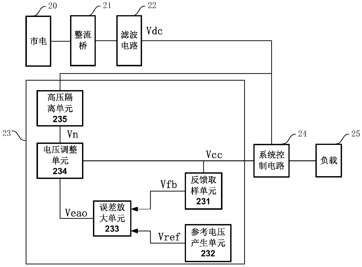
[0032] refer to figure 2 , is a schematic diagram of the structure of the power conversion device of the present invention.

[0033] The power conversion device includes: a rectifier bridge 21 electrically connected to the AC power supply 20, a filter circuit 22 electrically connected to the rectifier bridge 21, a system control circuit 24 electrically connected to the filter circuit 22, and a The load 25 electrically connected to the system control circuit; the power conversion device also includes an adaptive power supply circuit 23 .

[0034] The AC power supply 20 is commercial power, and the input end of the rectifier bridge 21 is electrically connected to the AC power supply 20 for rectifying the AC power output by the AC power supply 20 into DC power. The rectifier bridge 21 is a full...


PUM


Abstract

The invention discloses an adaptive power supply circuit. Power is directly extracted from DC high voltage after the mains supply is rectified and filtered through a rectifying bridge and a filteringcircuit, and stable DC low voltage is generated for providing power for a system control circuit. The adaptive power supply circuit is characterized by comprising a high voltage isolation unit, a voltage adjusting unit, a feedback sampling unit, a reference voltage generation unit, and an error amplifying unit, wherein the high voltage isolation unit is used for isolating DC high voltage fluctuation caused by mains supply fluctuation to output first stable DC voltage; the voltage adjusting unit, together with the error amplifying unit and the feedback sampling unit, forms a negative feedback control loop for stabilizing second DC voltage outputted by the voltage adjusting unit; the feedback sampling unit carries out proportional sampling on the second DC voltage outputted by the voltage adjusting unit to output feedback voltage; the reference voltage generation unit outputs stable reference voltage; and the error amplifying unit carries out error amplifying on the reference voltage outputted by the reference voltage generation unit and the feedback voltage outputted by the feedback sampling unit to generate error amplifying signals, and thus, the second DC voltage outputted by thevoltage adjusting unit is proportional to the reference voltage.

Description

technical field [0001] The invention relates to the technical field of integrated circuits, in particular to a power conversion device directly connected to the mains. Background technique [0002] With the rapid development of power semiconductor technology, power conversion devices, especially power conversion devices directly connected to the mains, are rapidly popularized. The power conversion device directly converts the power of the commercial power into a constant voltage or a constant current to supply a constant voltage load, or a constant current load similar to an LED. [0003] refer to figure 1 , Schematic diagram of the existing power conversion device architecture. The power supply circuit 13, the external resistor 14 and the external capacitor 15 cooperate with each other to directly rectify the mains 10 through the rectifier bridge 11, and the DC high voltage Vdc filtered by the filter circuit 12 is converted into a DC low voltage Vcc to supply power to the...

Claims


Application Information

Patent Timeline
Patent Type & Authority Patents(China)
IPC IPC(8): H02M7/217
CPCH02M7/217
Inventor 王俊杰
Owner SHANGHAI BRIGHT POWER SEMICONDUCTOR CO LTD
Why Eureka
Try Eureka