Guide wheel welding assembling tool

A guiding wheel and pairing technology, which is applied in welding equipment, auxiliary welding equipment, welding/cutting auxiliary equipment, etc., can solve problems such as scrapping, insufficient strength, large deformation of web plates, etc., to ensure the quality of pairing and prevent welding deformation , Guarantee the effect of positioning accuracy

Pending Publication Date: 2018-08-03
SHANTUI CONSTR MASCH CO LTD
View PDF8 Cites 4 Cited by
  • Summary
  • Abstract
  • Description
  • Claims
  • Application Information

AI Technical Summary

Problems solved by technology

During the assembly process of welded guide wheel bodies, due to the influence of welding deformation and the accuracy of parts dimensions, the left and right, upper and lower clearances and coaxiality of the laps between the rim and the web, and the hub and the web are often not guaranteed, resulting in During processing, some positions, such as the seal that plays a sealing role and the inner hole where the bearing bush is installed, cannot be processed, resulting in scrapping. This is particularly prominent in the welding of the guide wheel, which is a combination of multiple parts into a box-type structure.
[0003] At present, some enterprises use hydraulic presses for the combination of guide wheels. The equipment occupies a large area, is inconvenient to operate, and has low work efficiency. The residual stress is large, which affects the quality of the weld. In addition, the coaxiality of the rim and the hub cannot be guaranteed. It is necessary to increase the roughing allowance of the hub to prevent insufficient machining allowance of the hub due to unqualified coaxiality.
The combination tooling is not universal. A set of tooling for one product occupies a large area. The bolts on the pressure claws are tightened with an air gun to make the lap between the hub and the spoke plate smaller, but the pressure claws are in the form of welded seams. The strength is not enough, so there is still a gap between the hub and the rim, which does not meet the requirements of the drawing, low efficiency and high labor intensity
In summary, the existing problems are: 1. The tooling is not universal; 2. The problem of unqualified coaxiality between the hub and the rim has not been completely solved; 3. The pressure claws of the spoke plate adopt the form of imitation weld seam, and the overlapping joints There are still gaps; 4. Low efficiency, large footprint and high cost

Method used


Image

  • Guide wheel welding assembling tool
  • Guide wheel welding assembling tool
  • Guide wheel welding assembling tool

Examples


Embodiment 1

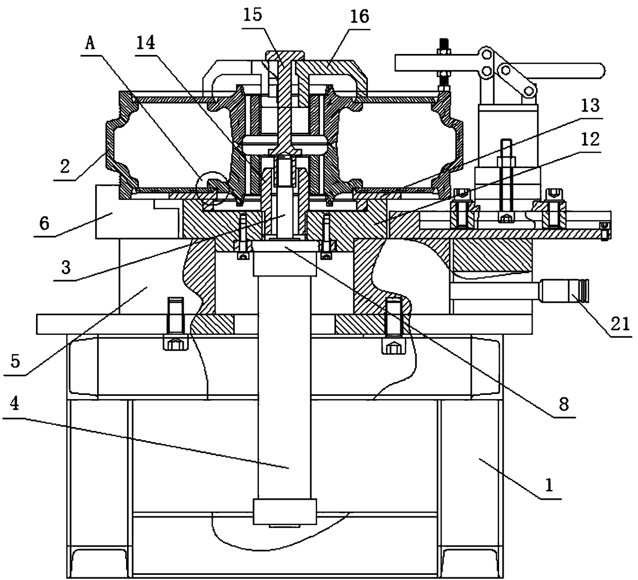
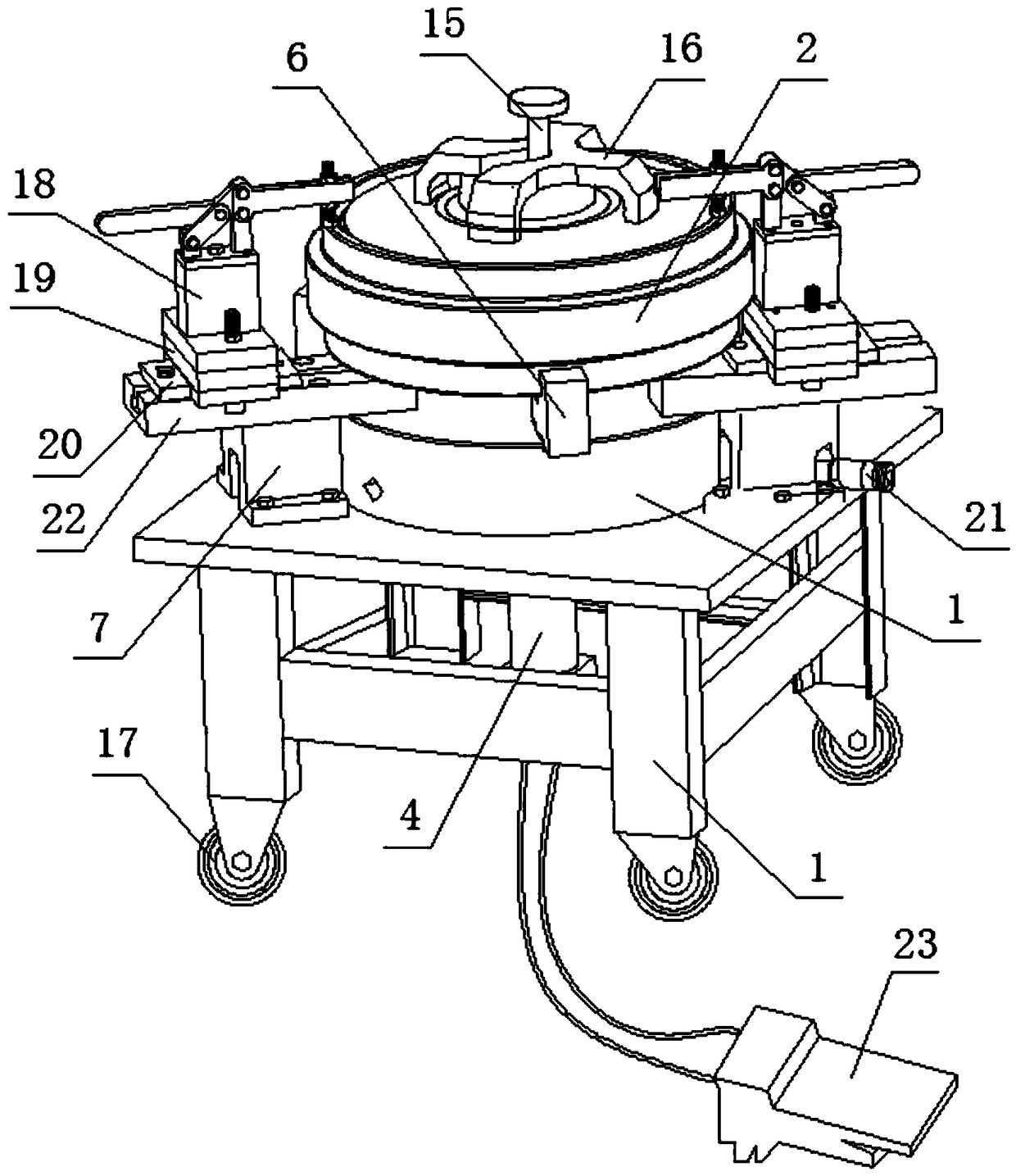
[0033] Such as Figure 1 to Figure 9 The shown guide wheel welding assembly tooling includes a reference platform, a positioning mechanism and a pressing mechanism. The reference platform includes a bracket 1 with a universal wheel 17 installed at the bottom, and the positioning mechanism includes a positioning plate 12, a tray 13, and a mandrel 14 And three-jaw chuck 5, the pressing mechanism comprises cylinder 4, cylinder flange 8, cylinder briquetting block 15, pressure claw 16 and fast pressing device, and the table top center of support 1 is provided with through hole, and three-jaw chuck 5 passes through Bolts are installed on the outer circumference of the through hole in the center of the table top of the bracket 1. The three-jaw chuck 5 is controlled by the wrench extension rod 21. The positioning plate 12 is arranged on the three-jaw chuck 5. There is a gap between the positioning plate 12 and the three-jaw chuck 5. Cooperate, the tray 13 is arranged on the positioni...

Embodiment 2

[0035] On the basis of Embodiment 1, the cylinder 4 is controlled by the pedal 23, which is convenient for controlling the cylinder 4. Two grooves are symmetrically arranged on the peripheral surface of the mandrel 14, which is convenient for the disassembly and assembly of the mandrel 14.

Embodiment 3

[0037] On the basis of Embodiment 1, the quick pressing mechanism 18 can adopt a corner cylinder or a hydraulic oil cylinder.

[0038] working principle:

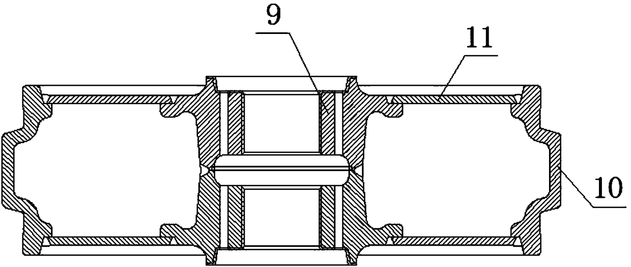
[0039] The wrench extension rod 21 controls the movement of the claws 6 of the three-jaw chuck 5, and the gap between the positioning plate 12 and the three-jaw chuck 5 is matched, and the claws 6 go deep into the groove of the positioning plate 12, limiting the rotation of the positioning plate 12 At the same time, the guide wheel 2 is clamped, and the gap between the tray 13 and the positioning plate 12 is matched to prevent the left and right and up and down movements of the tray 13, and play the role of fixing the lower web 11, ensuring that the lower web 11 is concentric with the hub 9, and the mandrel The 14 thread is installed on the positioning plate 12, which is easy to replace, and the surface is heat-treated to improve wear resistance. The distance between the two limit bosses on the cylinder pressure block 15 is...


PUM


Abstract

The invention relates to a guide wheel welding assembling tool, and belongs to the technical field of assembling tools. The guide wheel welding assembling tool comprises a reference platform, a positioning mechanism and a pressing mechanism; wherein the reference platform comprises a support which is provided with universal wheels at the bottom, the positioning mechanism comprises a positioning disc, a tray, a mandrel and a three-jaw chuck, and the pressing mechanism comprises an air cylinder, an air cylinder flange, an air cylinder pressing block, a pressing claw and a rapid pressing device.According to the tool, assembling is easy, manufacturing is easy, the used is convenient, hoisting is convenient, and the universality is achieved; welding assembling of guide wheels with different sizes can be realized by rapidly replacing the mandrel and the tray, and the occupied space is reduced; through pressing of the air cylinder, the labor intensity can be saved, and the efficiency can beimproved; the positioning mechanism adopts a split combined design, so that the positioning precision is guaranteed, and the mandrels of other products can be conveniently and quickly replaced; the rapid pressing device ensures that the lap joint clearance and the welding coaxiality of all the parts after assembling meet the standard requirements of a drawing, welding deformation is prevented, andthe assembling quality is guaranteed.

Description

technical field [0001] The invention relates to a guide wheel welding assembling tool, which belongs to the technical field of assembling tooling. Background technique [0002] The guide wheels on excavators and bulldozers mainly play a guiding role. The guide wheels are divided into cast type and welded type. The welded type guide wheels need to be riveted and welded together, that is, the assembly process, and then the whole ring is welded. Seam welding, heat treatment, processing, assembly, painting, etc. During the assembly process of welded guide wheel bodies, due to the influence of welding deformation and the accuracy of parts dimensions, the left and right, upper and lower clearances and coaxiality of the laps between the rim and the web, and the hub and the web are often not guaranteed, resulting in During processing, some positions such as the seal that plays a sealing role and the inner hole where the bearing bush is installed cannot be processed, resulting in sc...

Claims


Application Information

Patent Timeline
Patent Type & Authority Applications(China)
IPC IPC(8): B23K37/04
CPCB23K37/0435
Inventor 刘美娜赵燕堂张英超黄静华
Owner SHANTUI CONSTR MASCH CO LTD
Why Eureka
Try Eureka