High-precision sheet material width detecting and cutting device

A width detection and cutting device technology, applied in the field of measurement, can solve the problems of inconvenient detection, easy to break the whole plate, high cost, etc., and achieve the effect of low labor intensity, good cutting effect and low manufacturing cost

Pending Publication Date: 2018-08-03
泰州市龙洋木业有限公司
View PDF3 Cites 0 Cited by
  • Summary
  • Abstract
  • Description
  • Claims
  • Application Information

AI Technical Summary

Problems solved by technology

[0006] The purpose of the present invention is to provide a high-precision plate width detection and cutting device, so as to solve the problems of inconvenient detection in the prior art, such as low detection e

Method used


Image

  • High-precision sheet material width detecting and cutting device
  • High-precision sheet material width detecting and cutting device
  • High-precision sheet material width detecting and cutting device

Examples


specific Embodiment 1

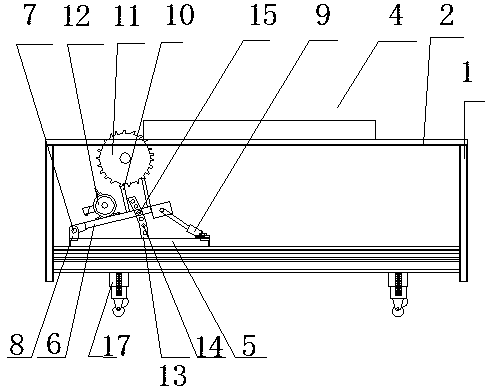
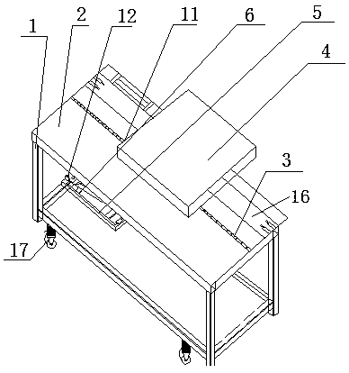
[0039] Specific embodiment 1: combine Figure 1-Figure 3 Shown: a high-precision plate width detection and cutting device, which includes a bracket 1, a cutting platform 2 is arranged on the bracket 1, a testing platform 16 is provided at the other end of the cutting platform 2, and a supporting device 17 is provided at the other end of the testing platform 16 ;

[0040] The cutting platform 2 is provided with a cutting groove 3, and the lower end of the cutting platform 2 is provided with a cutting mechanism. The cutting mechanism includes a fixed seat 5, on which a support swash plate 6 is installed, and the inclined lower end of the support swash plate 6 is hingedly installed by a pin shaft 7. The support seat 8 on the fixed seat 5, the inclined upper end of the support slant plate 6 is hinged to the piston rod of the overturn drive cylinder 9, the cylinder body of the overturn drive cylinder 9 is hingedly installed on the fixed seat 5, and the cutting seat 10 is installed ...

specific Embodiment 2

[0041] Specific embodiment 2: combine Figure 4 is a system block diagram of the plate non-destructive testing method in the embodiment of the present invention, such as Figure 4 shown, including the following aspects:

[0042] 1. The device 101 for detecting the thickness of the plate is used to measure the thickness of the plate. The measurement of thickness is mainly to measure the small variation of thickness. The thickness of each batch of wood in the factory is roughly the same, which can be expressed as (W+Δw). First, set this standard quantity as W, and only need to measure the variation Δw (Δw has positive and negative points) between each piece of wood and the standard value. By giving a fixed distance between a pair of displacement sensors, when the thickness changes, the displacement sensor the amount of indentation changes, the signal conditioning circuit through the

[0043] Road, the signal is collected into the controller, so as to calculate the thickness. ...

specific Embodiment 3

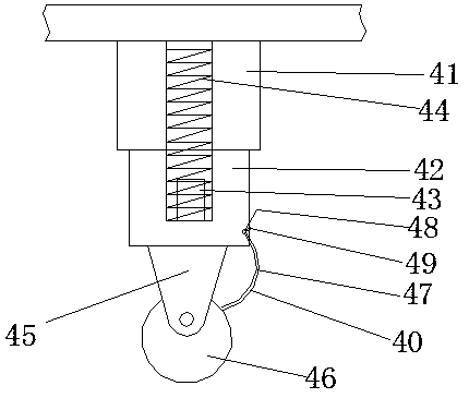
[0064] Specific embodiment 3, in combination image 3 A roller device 17 is provided below the cutting platform, and the roller device 17 includes a first telescopic rod 41, a second telescopic rod 42 slidably connected with the first telescopic rod 41, and a limiter set in the second telescopic rod 42. The position pin 43, the compression spring 44 sleeved on the limit pin 43, the roller support 45 connected to the bottom of the second telescopic rod 42, the roller 46 connected to the roller support 45 through the rotating shaft, and the rollers 46 evenly distributed on the outside of the roller 46 Groove, the limiting device 47 arranged on the outside of the second telescopic rod 42 .


PUM


Abstract

A high-precision sheet material width detecting and cutting device comprises a bracket, wherein the bracket is provided with a cutting platform, the other end of the cutting platform is provided witha test stand, and the other end of the test stand is provided with a supporting device; a cutting groove is formed in the cutting platform, the lower end of the cutting platform is provided with a cutting mechanism, four width sensors divided into two groups are arranged on the test stand, and the lower surface of the cutting platform is provided with roller devices. The high-precision sheet material width detecting and cutting device can be used as a support for cutting a sheet material, the length of the whole device can be adjusted by means of a movable rod according to specifications of different sheet materials, a movable frame can be additionally arranged on one side of a movable frame connecting rod, the movable frame can be fixed by buckling a rotary buckle on a fixed buckle, and the sheet material cut into small pieces can be vertically cut by means of rolling rods arranged on two sides of a main supporting frame, therefore, the high-precision sheet material width detecting and cutting device is suitable for the sheet materials no matter how large or small the sheet materials are, can be operated flexibly, and has the advantages of low manufacturing cost and low labor intensity of workers.

Description

technical field [0001] The invention relates to the field of measurement, in particular to a high-precision plate width detection and cutting device. Background technique [0002] With the increase of timber demand, the use of wood-based panels to replace logs and sawn timber has become one of the effective ways to efficiently utilize timber resources. The advantages of wood-based panels are: large format, good structure, convenient construction; low expansion and contraction rate, stable size, material [0003] It is more uniform than sawn timber and less prone to deformation and cracking; the veneer and various scraps used as raw materials for wood-based panels are easy to impregnate, so it can be used for various functional treatments (such as flame retardant, anti-corrosion, anti-shrinkage, wear-resistant, etc.); the range is wider The thickness level and density level have strong applicability; the bending and forming performance is better than that of sawn timber. Th...

Claims


Application Information

Patent Timeline
IPC IPC(8): G01B21/02B27B5/06B27B5/24B27B5/29
CPCG01B21/02B27B5/06B27B5/243B27B5/29
Inventor 王社平
Owner 泰州市龙洋木业有限公司
Why Eureka
Try Eureka