Multi-vehicle collaborative mapping method applied to automatic driving

An automatic driving and map technology, which is applied to road network navigators and other directions, can solve the problems of poor accuracy of single vehicles, large amount of calculation, and reduced map accuracy, achieve good robustness and robustness, realize collaborative positioning, and improve The effect of precision

Active Publication Date: 2018-08-03
SUN YAT SEN UNIV
View PDF5 Cites 16 Cited by
  • Summary
  • Abstract
  • Description
  • Claims
  • Application Information

AI Technical Summary

Problems solved by technology

[0006] The main problems of some current technologies are as follows: most of the current mapping technologies are aimed at the construction of bicycles; the mapping scheme needs more peripheral sensors, which are expensive; The problem of slowness and low efficiency; the existing collaborative mapping methods require a large amount of memory space, a large amount of calculation, and high CPU requirements; the existing collaborative mapping methods need to occupy a large amount of bandwidth resources;
Although this approach can maximize the detection field of view of a vehicle, the use of multiple sensors in a single vehicle has limits and limitations, and it is impossible to make further breakthroughs in the detection range.
[0008] In the process of building a single-vehicle map, with the prolongation of the cumulative running time of the algorithm, the cumulative error of the algorithm itself is getting larger and larger, and the accuracy of the built map is reduced, and due to the long-term single-vehicle mapping, it is easy to cause system instability
[0009] The existing multi-vehicle collaborative map construction method is based on graph features. The algorithm requires vehicles to send their own graph nodes to the entire network anytime and anywhere during the entire process, resulting in a decrease in network utilization and tight network bandwidth resources.
At the same time, after all the nodes in the network receive the data sent by the other party, they directly perform a large number of complex calculations without any preprocessing and other optimization operations, which requires a very high CPU cost for running the algorithm.

Method used


Image

  • Multi-vehicle collaborative mapping method applied to automatic driving
  • Multi-vehicle collaborative mapping method applied to automatic driving
  • Multi-vehicle collaborative mapping method applied to automatic driving

Examples


Embodiment Construction

[0036] The accompanying drawings are for illustrative purposes only, and should not be construed as limitations on this patent; in order to better illustrate this embodiment, certain components in the accompanying drawings will be omitted, enlarged or reduced, and do not represent the size of the actual product; for those skilled in the art It is understandable that some well-known structures and descriptions thereof may be omitted in the drawings. The positional relationship described in the drawings is for illustrative purposes only, and should not be construed as a limitation on this patent.

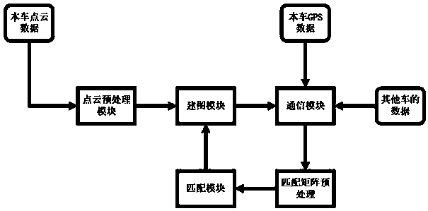
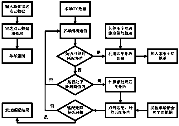
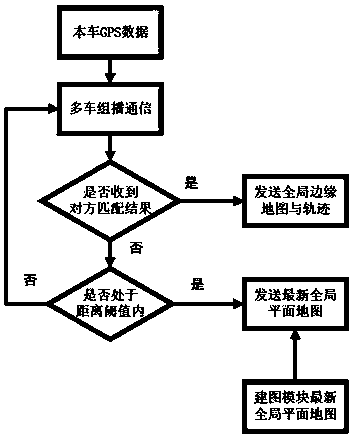
[0037] like figure 1 as shown, figure 1It is the data flow process of the algorithm: the point cloud data collected by the lidar and the input data stream collected by the GPS receiver are: the point cloud data of the vehicle, the GPS data of the vehicle and the data from other vehicles. Data from other cars includes real-time GPS of other cars, a certain frame of the global planar ...


PUM


Abstract

The invention relates to the technical field of intelligent driving, in particular to a multi-vehicle collaborative mapping method applied to automatic driving. The multi-vehicle collaborative mappingmethod applied to automatic driving comprises the following steps of step 1, data collection and perception; step 2, preprocessing of point cloud data; step 3, a local map and a global map; step 4, acommunication module; step 5, matching between two vehicles; step 6, after matching succeeds, sending a matching result to the opposite side by each vehicle; and step 7, after each vehicle receives aglobal edge map and trajectory data of the opposite side which are continuously sent by the opposite side, converting data through a matrix obtained by calculation in step 5 and then transferring a result to mileage calculation and mapping part to perform real-time collaborative mapping.

Description

technical field [0001] The present invention relates to the technical field of intelligent driving, and more specifically, relates to a multi-vehicle cooperative mapping method applied to automatic driving. Background technique [0002] LCM is a set of lightweight libraries and tools for messaging and data marshalling that can target high-bandwidth and low-latency real-time systems. It provides a publish / subscribe messaging model and automatic marshalling. LCM is implemented through UDP The multicast mechanism transmits customized data information under a certain multicast address and channel. Therefore, this method takes advantage of its real-time and multicast characteristics, and chooses it as a method for cooperative communication between vehicles. [0003] ROS (Robot Operating System) is a robot operating system. It provides the services that an operating system should have, including hardware abstraction, low-level device control, implementation of common functions, ...

Claims


Application Information

Patent Timeline
Patent Type & Authority Applications(China)
IPC IPC(8): G01C21/32
CPCG01C21/32
Inventor 黄凯李博洋轩辕哲张文权杨俊杰朱笛
Owner SUN YAT SEN UNIV
Why Eureka
Try Eureka