Scanning and tracking monitoring device and method

A technology for monitoring equipment and scanners, applied in the fields of medical science, diagnosis, instruments, etc., can solve the problems of complex and error-free tracking methods, and achieve the goal of reducing manual image inspection and scanning time, reducing risks, and improving diagnosis and treatment. Effect

Active Publication Date: 2021-11-05
DANMARKS TEKNISKE UNIV
View PDF4 Cites 0 Cited by
  • Summary
  • Abstract
  • Description
  • Claims
  • Application Information

AI Technical Summary

Problems solved by technology

[0005] For example, marker-free tracking methods based on 3D surface representations using structured light, depth sensors, and stereo vision systems are very complex and have a high risk of unpredictable errors

Method used


Image

  • Scanning and tracking monitoring device and method
  • Scanning and tracking monitoring device and method
  • Scanning and tracking monitoring device and method

Examples


Embodiment Construction

[0019] Various embodiments are described below with reference to the accompanying drawings. Like reference numerals refer to like elements throughout. Therefore, the same elements will not be described in detail with respect to the description of each drawing. It should also be noted that the drawings are only intended to facilitate description of the embodiments. They are not intended as an exhaustive description of the invention as claimed or as a limitation on the scope of the invention as claimed. Furthermore, an illustrated embodiment need not have all of the aspects or advantages shown. An aspect or advantage described in connection with a particular embodiment is not necessarily limited to that embodiment, and can be practiced in any other embodiment even if not so stated or not so explicitly described.

[0020] Throughout, the same reference numerals are used for the same or corresponding parts.

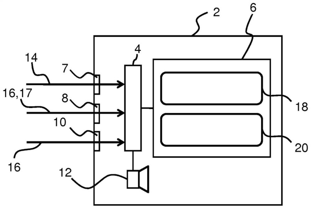
[0021] The scan monitoring device combines trace data with scanner d...


PUM


Abstract

A scanning monitoring device for medical imaging is disclosed, the scanning monitoring device comprising a controller unit and a display, wherein the controller unit is configured during a scanning session to obtain tracking data of a subject in a medical scanner ( 102); obtain scanner data indicative of operating parameters of the medical scanner (104); determine an output of a verification function based on the tracking data and the scanner data (106); and control a scan monitoring device based on the output of the verification function (108) . A notification signal may be provided in the event that a scan indicating an error is output.

Description

technical field [0001] The present disclosure relates to scan monitoring devices and related methods, in particular to scan monitoring devices such as Magnetic Resonance Imaging (MRI) and / or Positron Emission Tomography (PET) and / or Computed Tomography (CT) and / or Magnetoencephalography (MEG) and scanning monitoring equipment for medical imaging of radiation therapy. Background technique [0002] Motion tracking methods for motion correction in medical imaging have been intensively studied during the past few years, but no functional clinical tools exist for validated motion detection during biomedical scan acquisition. [0003] Motion during medical image acquisition can degrade the quality of medical images. Poor quality medical images can lead to costly rescans and at worst wrong diagnoses and treatments. Optimally, the medical imaging data should be corrected for any motion; however known tracking methods suffer from reliability constraints and thus reduce usability in...

Claims


Application Information

Patent Timeline
Patent Type & Authority Patents(China)
IPC IPC(8): A61B5/055A61B6/00A61B5/113
CPCA61B5/0064A61B5/055A61B5/1128A61B5/113A61B5/721A61B5/7405A61B5/742A61B6/032A61B6/037A61B6/4417A61B6/5264G01R33/283G01R33/56509A61B5/0037A61B6/461
Inventor 奥利纳·文特·奥勒森克劳斯·本杰明森
Owner DANMARKS TEKNISKE UNIV
Why Eureka
Try Eureka