MEMS bolometer sensor for measuring temperature in an exhaust pipe of an automotive vehicle

A technology of temperature sensor and exhaust manifold, applied in the direction of exhaust device, electrical control, fuel injection control, etc., can solve the problems of short signal response time, difficult engine control, harsh exhaust environment, etc., and achieve rapid temperature measurement Effect

Inactive Publication Date: 2018-08-03
ROBERT BOSCH GMBH
View PDF6 Cites 1 Cited by
  • Summary
  • Abstract
  • Description
  • Claims
  • Application Information

AI Technical Summary

Problems solved by technology

However, the resulting improved sensor can be expensive to produce and maintain, especially since the improved sensor is positioned directly in the harsh environment of the exhaust flow
Furthermore, when measurements vary between various cycles due to relatively small temperature values, it can be difficult to adequately control the engine without complex filtering and analysis of the sensor values
[0010] Other types of temperature sensors with shorter signal response times have been developed, such as bolometers, but such sensors have not been optimized to withstand the harsh exhaust environment

Method used


Image

  • MEMS bolometer sensor for measuring temperature in an exhaust pipe of an automotive vehicle
  • MEMS bolometer sensor for measuring temperature in an exhaust pipe of an automotive vehicle
  • MEMS bolometer sensor for measuring temperature in an exhaust pipe of an automotive vehicle

Examples


Embodiment Construction

[0031] To promote an understanding of the principles of the embodiments described herein, reference is now made to the drawings and descriptions in the following written specification. References are not intended to limit the scope of the subject matter. This disclosure also includes any alterations and modifications to the illustrated embodiments, and further applications of the principles of the described embodiments as would normally occur to one of ordinary skill in the art to which this document pertains.

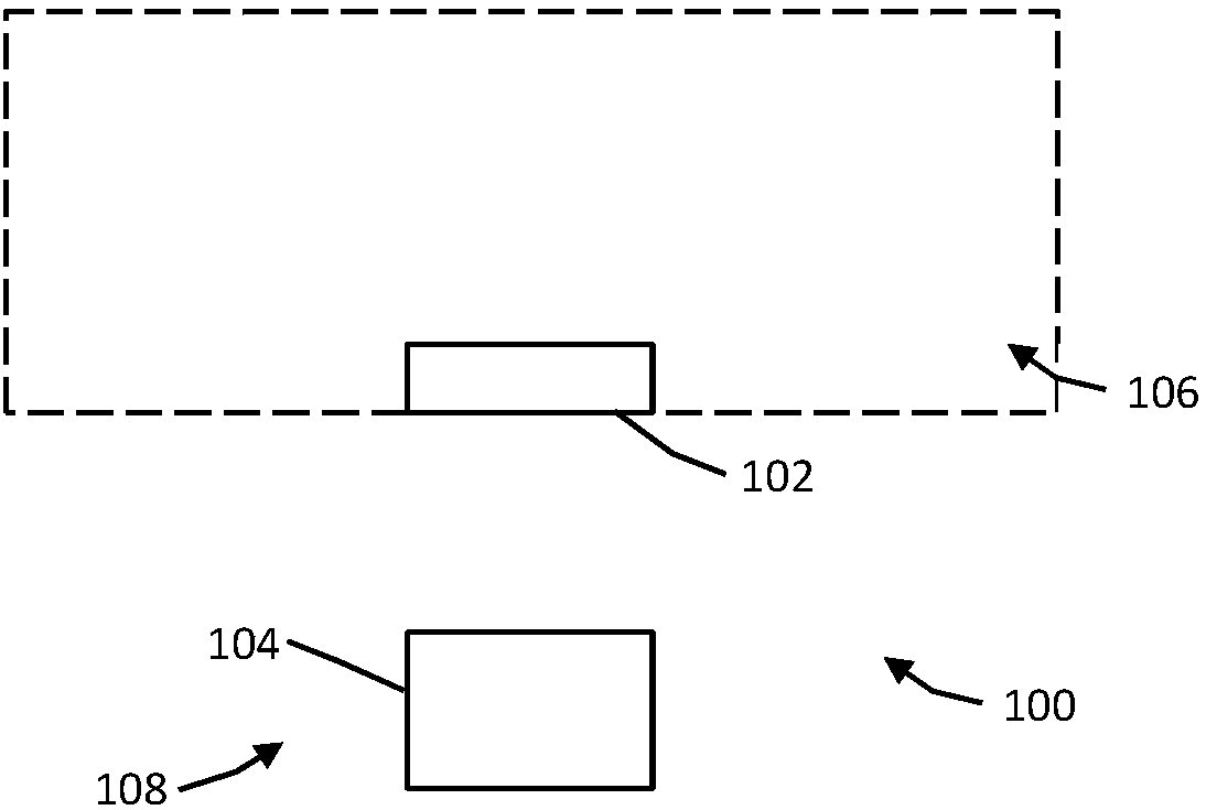
[0032] figure 1 is a schematic block diagram of a temperature sensing device 100 according to the present disclosure. The device 100 includes a probe unit 102 and a sensor unit 104 . The probe unit 102 is positioned such that it is substantially within the environment 106 to be measured. The probe unit 102 is exposed to the temperature of the environment 106 and is configured to reach a temperature corresponding to the temperature of the environment. The sensor uni...


PUM


Abstract

A control system for an internal combustion engine includes a temperature sensor and an engine controller. The sensor measures the temperature of exhaust gas passing through an exhaust manifold of theengine during each cycle. The controller selectively operates the engine in a first state and a second state. In the first, normal state, a quantity of fuel based on an open loop fuel mass command value is injected into the engine each cycle. In the second state, the controller determines a temperature of the exhaust gas during a normal cycle, injects the quantity and additional fuel into the engine during a second cycle, determines the temperature of the exhaust gas during the second cycle, compares the temperatures, and adjusts the command value for fuel to be injected each cycle when operating the engine in the first state.

Description

technical field [0001] The present disclosure relates generally to the field of temperature measurement, and more particularly to control systems and temperature sensors for automotive exhaust systems. Background technique [0002] Temperature is measured in many industrial and commercial systems and processes to provide the conditions required for system and process operation. By accurately measuring the temperature of systems and industrial processes, related equipment can operate at optimum efficiency. Temperature measurements on internal combustion engines can be particularly critical, as the efficiency of the engine can be directly related to the temperature at which the engine is operating. [0003] Some applications for temperature sensing have harsh or extreme environments that can affect a temperature sensor's ability to accurately determine temperature. For example, in some types of internal combustion engines, the temperature of the engine's exhaust gas can prov...

Claims


Application Information

Patent Timeline
Patent Type & Authority Applications(China)
IPC IPC(8): F02D41/02
CPCF01N13/008F01N13/10F01N2560/06F02D41/1446F02D41/2461F02D41/34F02D2200/0614Y02T10/40
Inventor W·菲舍尔N·拉维
Owner ROBERT BOSCH GMBH
Why Eureka
Try Eureka