Auxiliary clamp for machining

An auxiliary fixture and machining technology, applied in the direction of manufacturing tools, metal processing equipment, metal processing machinery parts, etc., can solve the problems of processing material movement, processing failure, processing inaccuracy, etc., and achieve the effect of avoiding damage

Inactive Publication Date: 2018-08-07
龙岩丽荣电子科技有限公司
View PDF4 Cites 3 Cited by
  • Summary
  • Abstract
  • Description
  • Claims
  • Application Information

AI Technical Summary

Problems solved by technology

[0003] The purpose of the present invention is to provide an auxiliary fixture for mechanical processing in order to solve the above problems, which solves the situation that the workers are inaccurate in machining or the processing material moves during the machining process, resulting in processing failure or accidents.

Method used


Image

  • Auxiliary clamp for machining
  • Auxiliary clamp for machining
  • Auxiliary clamp for machining

Examples


Embodiment Construction

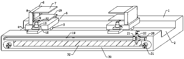
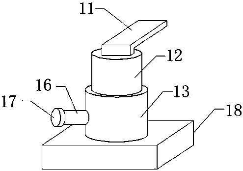
[0021] Such as Figure 1-4 As shown, this specific embodiment adopts the following technical solutions: an auxiliary fixture for mechanical processing, including a base 1, a No. block 3, the two sides of the No. 1 slider 3 are fixedly connected with a slide plate 4, and the slide plate 4 can play the role of auxiliary movement when the No. 1 slider 3 moves, and a bottom plate 5 is connected above the No. 1 slider 3, so A riser 6 is fixedly installed on the bottom plate 5, a fixed plate 7 is connected to one side above the riser 6, and a number of No. 2 chutes 8 are arranged below the fixed plate 7. No. 2 slider 9, one side of the No. 2 slider 9 is connected with a splint 10, and the splint 10 moves freely on the No. 2 chute 8 through the No. 2 slider 9, thereby changing the distance between the splint 10 and the fixed plate 7 , to fix the processing material, one side of the splint 10 is connected with the inner rod 12 through the connecting plate 11, the inner rod 12 is arra...


PUM


Abstract

The invention discloses an auxiliary clamp for machining. The clamp comprises a base, a first sliding groove is formed in the base, and multiple first sliding blocks are arranged in the first slidinggroove; sliding plates are fixedly connected to the two sides of each first sliding block, and baseplates are connected to the upper portions of the first sliding blocks. The auxiliary clamp for machining is provided with a scale ruler and pointers, clamping blocks can freely move on a sliding rail, and therefore the pointers can be freely moved through a first handle; a second rod is rotated through a second handle, the pointer at one end of each retractable rod and the pointer below the first rod form a right angle, and workers can more precisely conduct machining through scales of the scaleruler during machining; through arrangement of clamping plates and fixing plates, rotation rods can be rotated through rotation handles, gears at the peripheries of the rotation rods and a gear at one side of each inner rod are used for moving the inner rod up and down, connection plates drive the clamping plates to move up and down, the clamping plates and the fixing plates are used for fixing materials to be machined, and the situation is avoided that the materials are moved in the machining process, and accordingly the machining failure is caused.

Description

Technical field: [0001] The invention belongs to the technical field of mechanical equipment, and in particular relates to an auxiliary clamp for machining. Background technique: [0002] Machining refers to the process of changing the shape or performance of a workpiece through a mechanical device. Hot processing and cold processing of Shanghai Paini Technology can be divided into cutting processing and pressure processing according to the difference in processing methods. Common thermal processing includes heat treatment, forging, casting and welding. With the rapid development of modern mechanical processing and the rapid development of mechanical processing technology, many advanced mechanical processing technology methods have gradually emerged, such as micro-machining technology, rapid prototyping technology, precision ultra-precision processing technology, etc. Mechanical parts are made of Composed of several surfaces, to study the relative relationship of the surfa...

Claims


Application Information

Patent Timeline
Patent Type & Authority Applications(China)
IPC IPC(8): B23Q3/06B23Q17/00
CPCB23Q3/06B23Q17/003
Inventor 余金榕
Owner 龙岩丽荣电子科技有限公司
Why Eureka
Try Eureka