
Duffing oscillator detection method for chirp signal under strong noise background

A technology of linear frequency modulation signal and detection method, which is applied in the field of weak signal detection, and can solve problems such as time-consuming algorithm and complex structure

Active Publication Date: 2018-08-07
NORTHEAST DIANLI UNIVERSITY
View PDF3 Cites 8 Cited by
  • Summary
  • Abstract
  • Description
  • Claims
  • Application Information

AI Technical Summary

Problems solved by technology

In this method, the phase state discrimination method of the system adopts the Lyapunov index method, which has a complex structure and time-consuming algorithm, and the signal-to-noise ratio threshold of the analyzed signal must not be lower than -10dB

Method used


Image

  • Duffing oscillator detection method for chirp signal under strong noise background
  • Duffing oscillator detection method for chirp signal under strong noise background
  • Duffing oscillator detection method for chirp signal under strong noise background

Examples


Embodiment Construction

[0056] The present invention will be further described below using the drawings and specific embodiments.

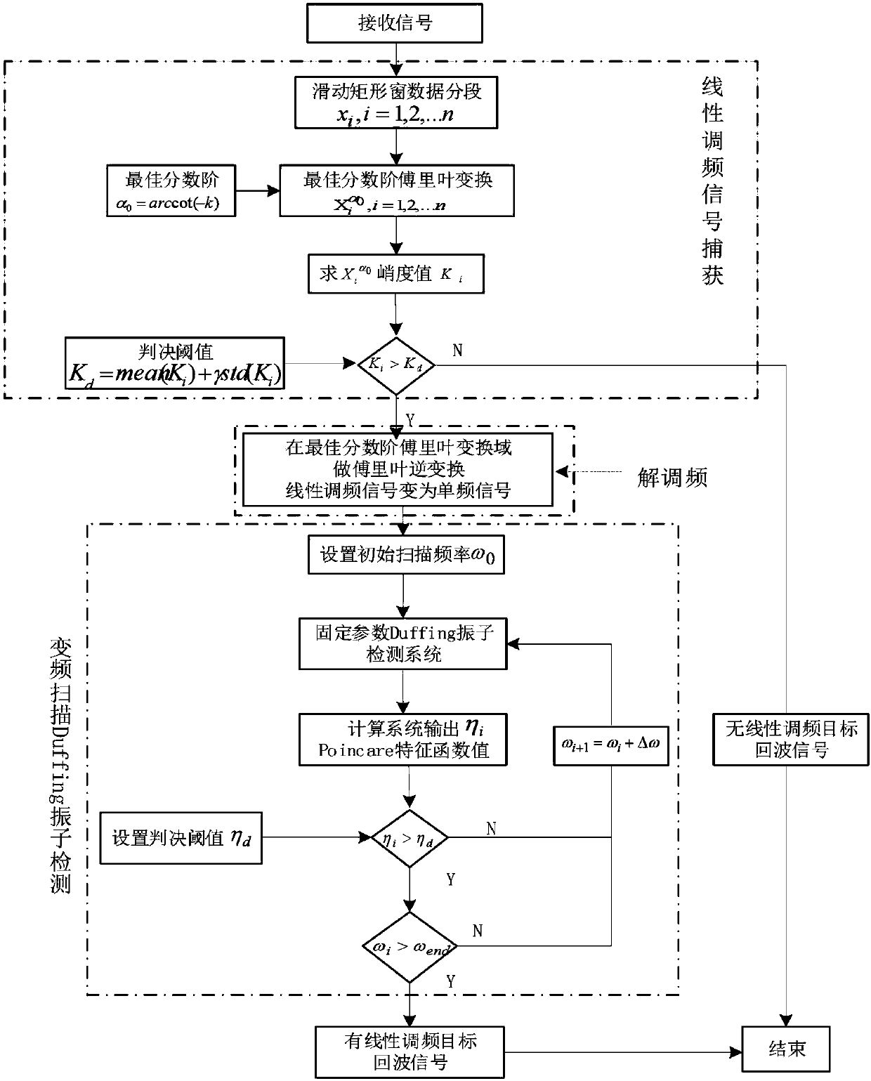
[0057] refer to figure 2 , a Duffing oscillator detection method of a chirp signal under a strong noise background of the present invention, comprising: interception and demodulation of the chirp signal, quantitative discrimination of the phase state of the Duffing oscillator based on the Poincare mapping characteristic function, and detection of the chirp signal The detection of frequency conversion Duffing vibrator consists of three parts.

[0058] 1) Interception and demodulation of linear frequency modulation signal

[0059] By introducing the optimal fractional Fourier transform domain spectral kurtosis parameter, the effective chirp echo signal data can be predicted from the received signal for further analysis and processing, and the FRFT inverse transform is performed on the effective echo signal to realize demodulation , which is to demodulate the chirp signa...


PUM


Abstract

The invention discloses a Duffing oscillator detection method for a chirp signal under a strong noise background. The method is characterized by comprising the following steps: intercepting and demodulating a chirp signal; carrying out quantitative determination on the phase state of a Duffing oscillator based on a Poincare mapping feature function; and carrying out frequency conversion Duffing oscillator detection of a chirp signal. When the method is used for detection, the built-in driving force frequency of the Duffing oscillator system is changed and thus a single-frequency signal component in the demodulated frequency signal is scanned; and whether the system has a resonance phenomenon is determined based on the Poincare mapping feature function value outputted by the detection system, so that the chirp signal detection under a low-signal-to-noise-ratio background is realized. The method has advantages of good scientific and reasonable properties, high applicability and good effect.

Description

technical field [0001] The invention belongs to the technical field of weak signal detection, and relates to a Duffing oscillator detection method of a linear frequency modulation signal under a strong noise background. Background technique [0002] The chirp signal is usually used as the transmission signal of radar and active sonar to detect underwater targets. Due to the engineering requirement for the resolution of the transmission signal parameters, the chirp signal is usually a pulse compression signal with a large time-width-bandwidth product. When the transmission power is constant, the spectrum of the transmitted signal is expanded by frequency modulation technology. According to Parseval's theorem, spectrum expansion will reduce the power spectral density of the signal. At the same time, due to the characteristics of target scattering and the existence of strong interference factors in the external environment, the chirp target echo signal scattered or reflected b...

Claims


Application Information

Patent Timeline
IPC IPC(8): G01H17/00
CPCG01H17/00
Inventor 李楠董爽赵妍张爱辉孟联刘宇群
Owner NORTHEAST DIANLI UNIVERSITY
Learn More