
Bridge health monitoring method and system

A health monitoring system and health monitoring technology, applied in special data processing applications, instruments, electrical digital data processing, etc., can solve the problems of consuming a lot of manpower and material resources, it is difficult to identify damage, and the life of components and structures is low. Save manpower and material resources, facilitate maintenance and management, improve reliability and efficiency

Inactive Publication Date: 2018-08-07
SHENZHEN MUNICIPAL DESIGN & RES INST
View PDF3 Cites 17 Cited by
  • Summary
  • Abstract
  • Description
  • Claims
  • Application Information

AI Technical Summary

Problems solved by technology

Monitoring aims to obtain the cross-sectional stress, strain, and deflection of different parts of the bridge. The disadvantages of this monitoring system are as follows: ①The monitoring target is mainly static parameters (stress, strain, deflection, etc.), and the response is often local structural stresses. Force conditions and local mechanical properties; ②It is difficult to identify damage when the load transmission path is inconsistent with the damaged part; ③The normal operation of embedded components such as sensors cannot be guaranteed, and the life of components is far lower than that of structures and is expensive; ④ It is difficult to realize online real-time monitoring, and it is difficult to capture the specific moment of overload operation. At the same time, there is no proper method to process and analyze the massive test data; ⑤ It takes a lot of manpower and material resources to realize online real-time monitoring

Method used


Image

  • Bridge health monitoring method and system
  • Bridge health monitoring method and system
  • Bridge health monitoring method and system

Examples


specific Embodiment approach

[0049] A specific implementation of a bridge health monitoring method is as follows:

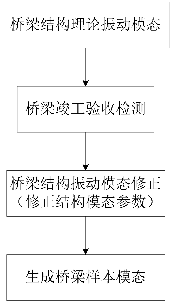
[0050] 1. If figure 1As shown, the three-dimensional information BIM model of the bridge is established, and the structural analysis software (such as ANSYS, Midas, ABAQUS, etc.) is used to analyze and calculate the vibration mode of the bridge model to obtain the theoretical vibration mode of the bridge structure. When the bridge is completed and accepted, the dynamic mode detection of the bridge structure is carried out, and the structural mode parameters are corrected by comparing the measured bridge dynamic mode and the theoretical dynamic mode, and the corrected bridge dynamic mode is obtained, which is used as a structural dynamic sample model for operation monitoring. To carry out long-term monitoring of bridge health status (including seismic performance).

[0051] 2. During the operation of the bridge, use the vibration data acquisition components placed on the bridge (such as piez...


PUM


Abstract

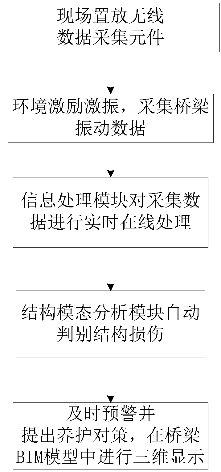
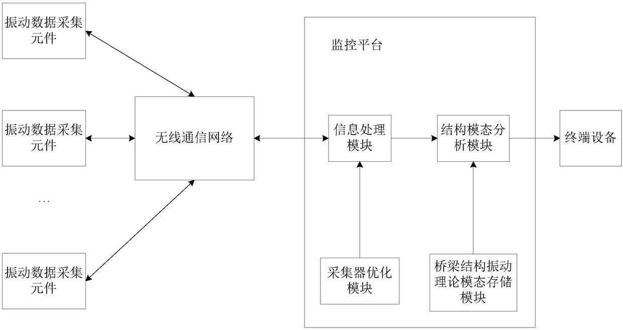
The invention discloses a bridge health monitoring method and system. The method comprises the steps of S1, building a bridge structure theory vibration modal; S2, collecting bridge vibration data; S3, utilizing an information processing module, and performing real-time online data processing on the bridge vibration data; S4, utilizing a structure modal analysis module, and on the basis of the bridge vibration data and the neural network computing technology, automatically performing intelligent judgment on structure damage. By means of the wireless communication technology, the bridge structure dynamic modal, and the structure damage neural network recognition technology, the problems that in the prior art, only a local bridge structure is reflected, the bridge damage is not likely to berecognized, the cost of a data collection sensor is high, the service life is short, mass data cannot be analyzed in real time, online real-time monitoring is performed, and time and labor are wastedare solved, the automatic bridge health monitoring system can achieve integrated bridge structure analysis, automatic damage recognition and online real-time mass data analysis, and a large number ofmanpower and material resources are saved.

Description

technical field [0001] The invention relates to the technical field of bridge engineering, in particular to a bridge health monitoring method and system. Background technique [0002] BIM model: Building Information Modeling, Building Information Modeling. [0003] NPU: Neural-network Processing Unit, neural network processor. [0004] The bridge is a key node project related to the lifeline of the national economy and the lifeline of the city. In order to ensure the safe operation of the bridge structure, it is necessary to establish a bridge structure health monitoring system. Bridge health monitoring is an important part of bridge operation and maintenance management. By monitoring bridges, it can provide theoretical support for basic maintenance, and more importantly, avoid sudden disasters caused by bridge damage. [0005] Traditional bridge health monitoring is mainly to pre-set (or embed) mechanical sensors, temperature sensors and other components on the bridge, an...

Claims


Application Information

Patent Timeline
IPC IPC(8): G06F17/50
CPCG06F30/13
Inventor 陈宜言何晓晖王用中宗周红董桔灿王健
Owner SHENZHEN MUNICIPAL DESIGN & RES INST
Learn More