Anti-magnetic-suspension-based flowed energy harvester
A technology of airflow energy and magnetic levitation, which is applied in the direction of holding devices, electrical components, generators/motors, etc. using magnetic attraction or thrust, and can solve the problem of inability to realize low-speed airflow conversion.
- Summary
- Abstract
- Description
- Claims
- Application Information
AI Technical Summary
Problems solved by technology
Method used
Image
Examples
Embodiment 1
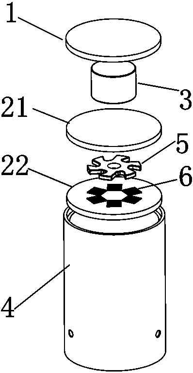
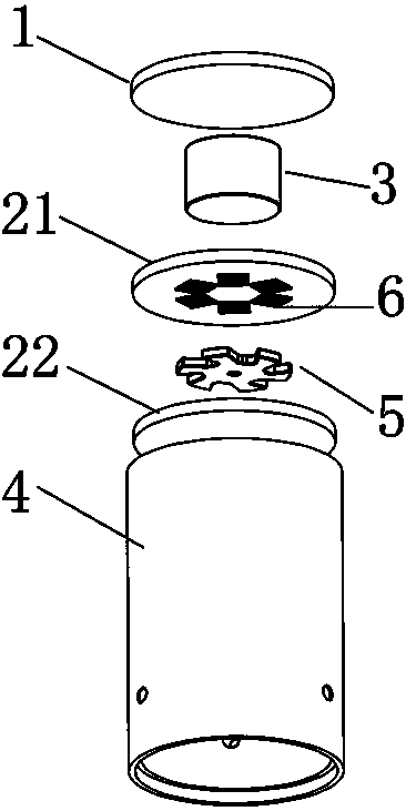
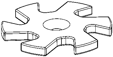
[0024] Such as Figure 1-6 As shown, a kind of airflow energy harvester based on anti-magnetic levitation includes a shell 4 and a cover plate 1, the top of the shell 4 is provided with a cover plate 1, and an anti-magnetic levitation system and an induction coil 6 are arranged inside the shell 4, and the anti-magnetic levitation The magnetic levitation system includes a lifting permanent magnet 3, an upper pyrolytic graphite plate 21, a magnetic rotor 5 and a lower pyrolytic graphite plate 22 from top to bottom, the lifting permanent magnet 3 is arranged below the cover plate 1, and the lifting permanent magnet 3 adopts The cylindrical NdFeB magnet whose brand is N52 has a diameter of 15mm and a thickness of 10mm. The magnet rotor 5 is freely suspended between the upper pyrolytic graphite plate 21 and the lower pyrolytic graphite plate 22, without contact with any object, and the magnetization direction of the lifting permanent magnet 3 is the same as that of the magnet rotor...
Embodiment 2
[0030] Such as Figure 1-6 As shown, a kind of airflow energy harvester based on anti-magnetic levitation includes a shell 4 and a cover plate 1, the top of the shell 4 is provided with a cover plate 1, and an anti-magnetic levitation system and an induction coil 6 are arranged inside the shell 4, and the anti-magnetic levitation The magnetic levitation system includes a lifting permanent magnet 3, an upper pyrolytic graphite plate 21, a magnetic rotor 5 and a lower pyrolytic graphite plate 22 from top to bottom. The cylindrical NdFeB magnet has a diameter of 12mm and a thickness of 10mm. A magnet rotor 5 is arranged between the upper pyrolytic graphite plate 21 and the lower pyrolytic graphite plate 22, and the magnet rotor 5 is freely suspended between the pyrolytic graphite plates without contacting any objects. The upper pyrolytic graphite plate 21 A total of 16 induction coils 6 are arranged on the inner surface of the lower pyrolytic graphite plate 22. The magnetization...
Embodiment 3
[0035] Such as Figure 1-6 As shown, the present embodiment is an airflow energy harvester based on anti-magnetic levitation, including a housing 4 and a cover plate 1, the upper part of the housing 4 is provided with a cover plate 1, and the housing 4 is provided with an anti-magnetic levitation system and an induction coil 6 , the anti-magnetic levitation system includes a lifting permanent magnet 3, an upper pyrolytic graphite plate 21, a magnetic rotor 5 and a lower pyrolytic graphite plate 22 from top to bottom, and the lifting permanent magnet 3 is arranged under the cover plate 1, and adopts The cylindrical NdFeB magnet whose brand is N52 has a diameter of 15mm and a thickness of 10mm. A magnet rotor 5 is arranged between the upper pyrolytic graphite plate 21 and the lower pyrolytic graphite plate 22, and the magnet rotor 5 is freely suspended without contacting any object. The upper pyrolytic graphite plate 21 and the lower pyrolytic graphite plate 22 A total of 12 in...
PUM
| Property | Measurement | Unit |
|---|---|---|
| Thickness | aaaaa | aaaaa |
| Diameter | aaaaa | aaaaa |
| Thickness | aaaaa | aaaaa |
Abstract
Description
Claims
Application Information
 - R&D
- Intellectual Property
- Life Sciences
- Materials
- Tech Scout
- Unparalleled Data Quality
- Higher Quality Content
- 60% Fewer Hallucinations
Browse by: Latest US Patents, China's latest patents, Technical Efficacy Thesaurus, Application Domain, Technology Topic, Popular Technical Reports.
© 2025 PatSnap. All rights reserved.Legal|Privacy policy|Modern Slavery Act Transparency Statement|Sitemap|About US| Contact US: help@patsnap.com


