
Manufacturing method of ITO film

A production method and thin film technology, which is applied in the field of flat panel display, can solve the problems of high film resistance, poor visible light transmittance, and affecting the film formation rate of ITO thin films, so as to achieve the effect of reducing resistance and improving transmittance

Active Publication Date: 2018-08-10
TRULY HUIZHOU SMART DISPLAY
View PDF10 Cites 1 Cited by
  • Summary
  • Abstract
  • Description
  • Claims
  • Application Information

AI Technical Summary

Problems solved by technology

[0003] The traditional method of depositing ITO thin film adopts magnetron sputtering method. During the low-temperature deposition process, Sn exists in the form of SnO in the ITO thin film, and In exists in the form of InO in the ITO thin film, resulting in low carrier concentration and high film resistance.
Since SnO and InO are dark brown, they have poor transmittance to visible light
Moreover, the adhesion on the surface of the film-forming plate affects the film-forming rate of the ITO film. The high room temperature of the film-forming chamber leads to an increase in the temperature of the film-forming plate, which makes the ITO film a polycrystalline structure, which is not conducive to the subsequent use of oxalic acid under low temperature conditions. Etching
However, the above-mentioned problems exist in the traditional thin film manufacturing process, which makes the parameters of the produced ITO thin film lower and cannot meet the higher requirements of the display screen.

Method used


Image

  • Manufacturing method of ITO film
  • Manufacturing method of ITO film
  • Manufacturing method of ITO film

Examples


Embodiment Construction

[0021] In order to make the above objects, features and advantages of the present invention more comprehensible, specific implementations of the present invention will be described in detail below in conjunction with the accompanying drawings. In the following description, numerous specific details are set forth in order to provide a thorough understanding of the present invention. However, the present invention can be implemented in many other ways different from those described here, and those skilled in the art can make similar improvements without departing from the connotation of the present invention, so the present invention is not limited by the specific embodiments disclosed below.

[0022] In the description of the present invention, it should be understood that the terms "first" and "second" are used for description purposes only, and cannot be interpreted as indicating or implying relative importance or implicitly indicating the quantity of indicated technical featu...


PUM


Abstract

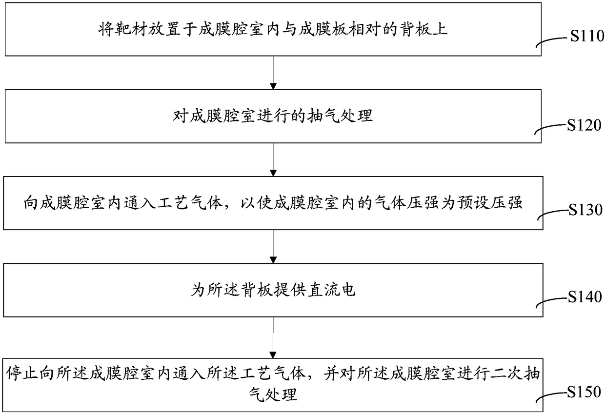
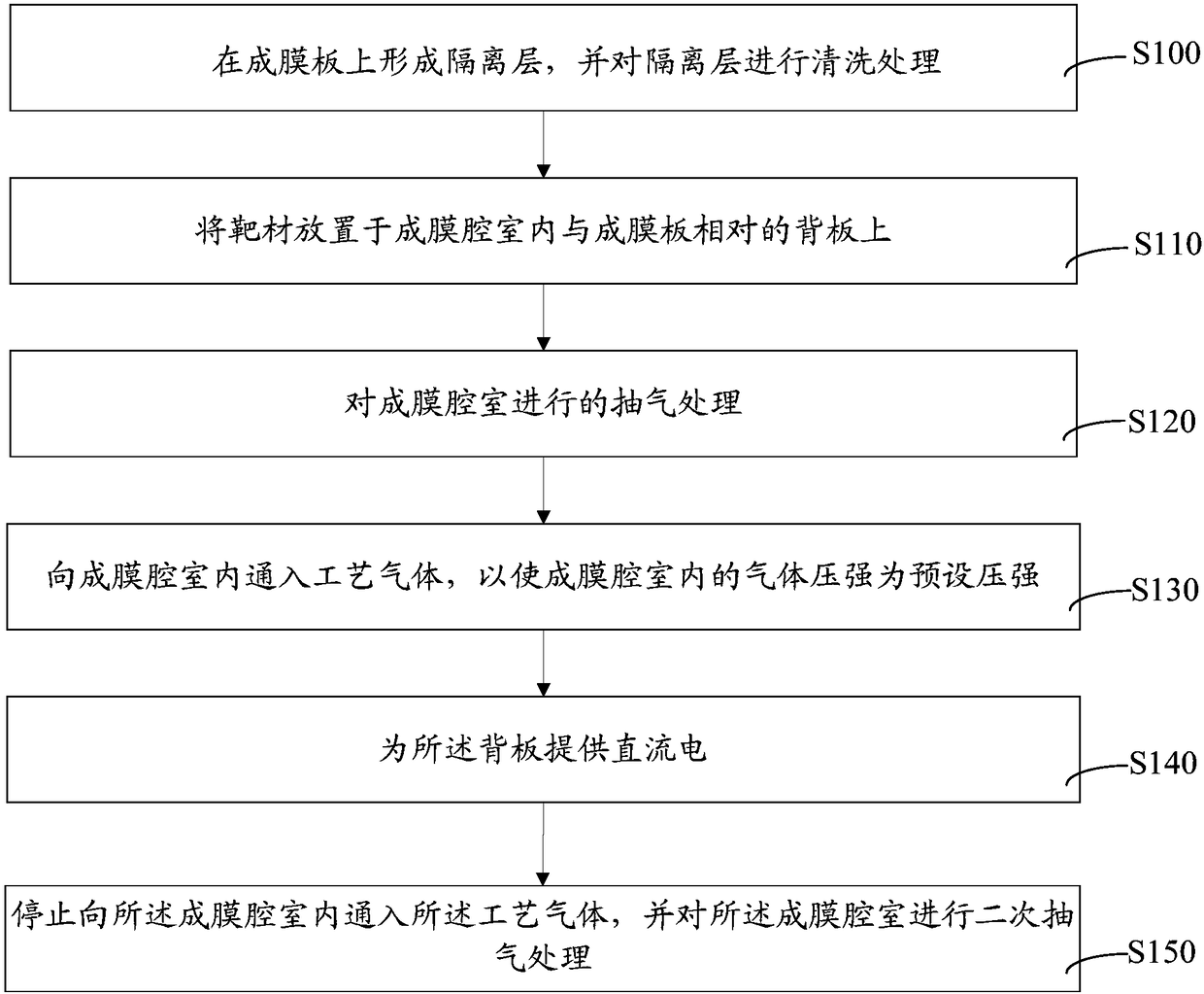
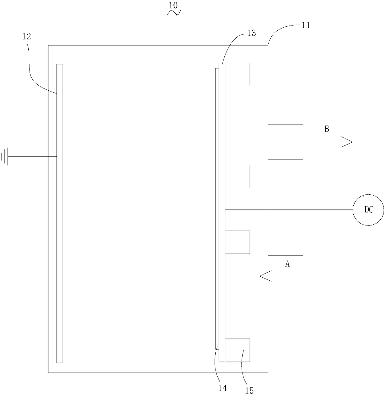
The invention relates to a manufacturing method of an ITO film. The manufacturing method comprises the following steps of: placing a target material on a backboard which is positioned inside a film forming chamber and is opposite to a film forming plate; exhausting air from the film forming chamber; charging process gas into the film forming chamber to make sure that the gas pressure inside the film forming chamber is equal to preset pressure; providing direct-current electricity for the backboard; and stopping charging the process gas into the film forming chamber and exhausting the gas fromthe film forming chamber again. Under a low-temperature condition, the process gas is charged into the film forming chamber to remove particles on the surface of an isolating layer so that the adhesiveness of a film on the film forming plate is improved. By the primary air exhaust treatment, the inside of the film forming chamber can reach a high-vacuum state, the cleanness inside the film formingchamber is guaranteed, and the compactness of the film is improved; by the secondary gas exhaust treatment, foreign materials on the surface of the film are removed, the over-standard rate of defectscaused by the foreign materials in a subsequent manufacturing process is reduced, and thus the film meeting higher parameter requirements is obtained.

Description

technical field [0001] The invention relates to the field of flat panel display technology, in particular to a method for manufacturing an ITO thin film. Background technique [0002] ITO (Indium Tin Oxide, tin-doped indium oxide, also known as indium tin oxide) film, as a transparent conductive material, is the most commonly used transparent electrode for liquid crystal displays, plasma displays, electroluminescent displays, touch screens, solar cells and other electronic instruments film material. ITO film is a body-centered cubic ferromanganese ore N-type semiconductor. Its optical and electrical properties can be quantitatively studied by Drude model. ITO film generally has an optical band gap greater than the energy of visible photons (3.1eV), and visible light cannot cause this Excited by proof, so it is not absorbing to light and transparent to visible light. [0003] The traditional method of depositing ITO thin film adopts magnetron sputtering method. During the l...

Claims


Application Information

Patent Timeline
IPC IPC(8): C23C14/35C23C14/08C23C14/58
CPCC23C14/0036C23C14/086C23C14/35C23C14/5873
Inventor 何海山刘力明黄伟东李建华
Owner TRULY HUIZHOU SMART DISPLAY
Learn More