Method for continuously and quickly preparing SiC fiber surface BN coating

A fiber surface and coating technology, applied in coating, metal material coating process, gaseous chemical plating, etc., can solve the problems of easy decomposition of BN, uneven coating, slow deposition speed, etc., to avoid surface crusting Effect

Active Publication Date: 2018-08-10
CENT SOUTH UNIV
View PDF4 Cites 8 Cited by
  • Summary
  • Abstract
  • Description
  • Claims
  • Application Information

AI Technical Summary

Problems solved by technology

[0009] On the one hand, the current vapor deposition method for depositing BN coatings on SiC fibers is to weave the SiC fibers first, and then deposit the coating. The coating formed in this way is not uniform and the deposition speed is slow. The braid has a certain thickness, and the distance between the fibers is relatively close, and the permeability of the sediment decreases with the deposition time, resulting in insufficient deposition inside the braid and the formation of defects; eventually the formed coating is uneven. In addition, in order to make The inside and outside of the braid is deposited evenly, and the deposition rate outside the braid needs to be controlled to prevent surface crusting or pore plugging; therefore, the deposition rate is slow;
[0010] On the other hand, since the BN coating formed during vapor deposition is in an amorphous state, its stability is poor, it is easy to decompose, and it is easy to react in the air. It needs heat treatment in the later stage to convert the crystal form into a crystalline BN coating. Stability, however, deposition and high temperature heat treatment need to be carried out in different equipment, so that in the process of equipment conversion, BN is easily decomposed, resulting in the BN formed by deposition cannot finally obtain a stable crystal form

Method used


Image

  • Method for continuously and quickly preparing SiC fiber surface BN coating
  • Method for continuously and quickly preparing SiC fiber surface BN coating
  • Method for continuously and quickly preparing SiC fiber surface BN coating

Examples


Embodiment 1

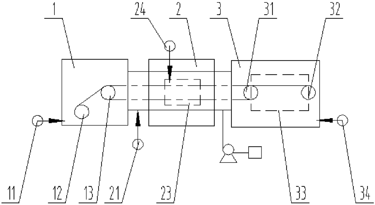
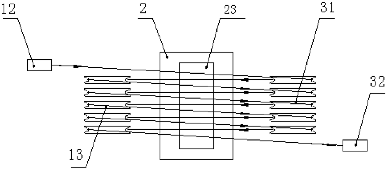
[0065] First, the vapor deposition device 2 and the heat treatment device 3 are evacuated through the vacuum system. Since the wire releasing device 1 and the vapor deposition device 2 are in a connected state, they will also be evacuated. The gas port C11 is fed with argon gas, and the gas inlet F34 of the heat treatment device 3 is fed with nitrogen gas, and the gas replacement is performed 3 times.

[0066] After the gas replacement is completed, the deposition stage is carried out. The air inlet C11 of the wire feeding device 1 continues to be fed with argon gas, and the flow rate of the argon gas is controlled to be 1.0 L / min. The nitrogen gas is continuously fed into the air inlet F34 of the heat treatment device 3, and the nitrogen gas The flow rate is 1.0L / min.

[0067] BI used in the deposition process 3 and NH 3 As the source gas, H 2 As diluent gas, NH 3 The deposition furnace is carried out from the second gas inlet 21 of the vapor deposition device 2, BI 3 Af...

Embodiment 2

[0071] Vacuumize the vapor deposition device 2 and the heat treatment device 3 through the vacuum system first, because the wire releasing device 1 and the vapor deposition device 2 are in a connected state, they will also be vacuumed, and then respectively from the air inlet C11 of the wire releasing device 1 Argon gas was introduced, and nitrogen gas was introduced from the gas inlet F34 of the heat treatment device 3, and the gas replacement was performed 3 times.

[0072] After the gas replacement is completed, the deposition stage is carried out. The air inlet C11 of the wire feeding device 1 continues to be fed with argon gas, and the flow rate of the argon gas is controlled to be 4.0 L / min. The nitrogen gas is continuously fed into the air inlet F34 of the heat treatment device 3, and the nitrogen gas The flow rate is 1.0L / min.

[0073] BCl was used in the deposition process 3 and NH 3 As the source gas, H 2 As diluent gas, NH 3 Carry out in the deposition furnace f...

Embodiment 3

[0077] First, the vapor deposition device 2 and the heat treatment device 3 are evacuated through the vacuum system. Since the wire releasing device 1 and the vapor deposition device 2 are in a connected state, they will also be evacuated. The gas port C11 is fed with argon gas, and the gas inlet F34 of the heat treatment device 3 is fed with nitrogen gas, and the gas replacement is performed 3 times.

[0078] After the gas replacement is completed, the deposition stage is carried out. The air inlet C11 of the wire feeding device 1 continues to be fed with argon gas, and the flow rate of the argon gas is controlled to be 10.0L / min. The nitrogen gas is continuously fed into the air inlet F34 of the heat treatment device 3, and the nitrogen gas The flow rate is 4.0L / min.

[0079] BCl was used in the deposition process 3 and NH 3 As the source gas, H 2 As diluent gas, NH 3 Carry out in the deposition furnace from the second gas inlet 21 of vapor deposition device 2, BCl 3 an...


PUM

PropertyMeasurementUnit
thicknessaaaaaaaaaa
thicknessaaaaaaaaaa
thicknessaaaaaaaaaa

Abstract

The invention discloses a method for continuously and quickly preparing a SiC fiber surface BN coating. By utilizing a yarn winding and unwinding device, after a SiC fiber is subjected to amorphous form BN interface deposition under movement, the crystal-state BN coating can be directly converted, so that the problem that in the prior art, no amorphous form BN is decomposed during a deposition-heat treatment conversion process is effectively avoided. A microwave heating manner is adopted during a heat treatment process, so that a uniform and flawless stable crystal structure is finally obtained; and in addition, the yarn winding and unwinding device adopts a multi-roller system, so that cyclic deposition is carried out during a deposition process, and the crystal-state BN coating with therequired thickness can be quickly obtained.

Description

technical field [0001] The invention belongs to the field of composite materials, in particular to a method for continuously and rapidly preparing a BN coating on the surface of SiC fibers. Background technique [0002] With the rapid development of science and technology, composite materials also emerge in endlessly. Ceramic matrix composites have attracted increasing attention because of their excellent properties such as high temperature resistance, corrosion resistance, wear resistance and light relative density. Among them, SiC fiber-reinforced composite materials have been widely used in aerospace and aerospace fields, and fiber reinforcement is one of the main methods to improve the performance of composite materials. [0003] As a coating that can improve the performance of SiC fibers, BN coating has the following advantages: [0004] 1. The toughening is obvious. Both BN and PyC are weak coatings, which can greatly improve the bending strength of SiC fibers with r...

Claims


Application Information

Patent Timeline
Patent Type & Authority Applications(China)
IPC IPC(8): C23C16/34C23C16/56C23C16/54
CPCC23C16/342C23C16/545C23C16/56
Inventor 阳海棠黄小忠陆子龙彭立华黎尧
Owner CENT SOUTH UNIV
Why Eureka
Try Eureka