Square multi-cavity steel plate and concrete combination beam

A technology of concrete and composite beams, applied in the direction of load-bearing elongated structural components, structural elements, building components, etc., can solve the problems of poor crack resistance, affect the progress of the project, reduce the service life of components, etc., and achieve strong transverse Restraining effect, improving construction efficiency and reducing production cost

Inactive Publication Date: 2018-08-10
CHINA UNIV OF PETROLEUM (EAST CHINA)
View PDF0 Cites 0 Cited by
  • Summary
  • Abstract
  • Description
  • Claims
  • Application Information

AI Technical Summary

Problems solved by technology

[0002] At present, urban viaducts, long-span bridges, industrial and civil buildings, etc. are mainly cast-in-place concrete structures. This construction method has a long construction period, which greatly affects the progress of the project. It brings inconvenience to life, causes environmental pollution, and increases social costs
Moreover, the traditional concrete components commonly used in buildings are heavy and unsuitable for long-span structures; at the same time, the crack resistance is poor, and cracks are exposed, which reduces the service life of the components. On-site pouring has many construction procedures, requires maintenance, and the construction period is long and affected by the construction environment. and climatic conditions; traditional concrete components cannot well restrain the lateral sliding of concrete under stress, so that the compressive strength of concrete cannot be fully exerted; in addition, traditional concrete components need formwork support when pouring, and the formed concrete The integrity of the component itself is relatively lacking, and the quality is not easy to control

Method used


Image

  • Square multi-cavity steel plate and concrete combination beam
  • Square multi-cavity steel plate and concrete combination beam
  • Square multi-cavity steel plate and concrete combination beam

Examples


Embodiment Construction

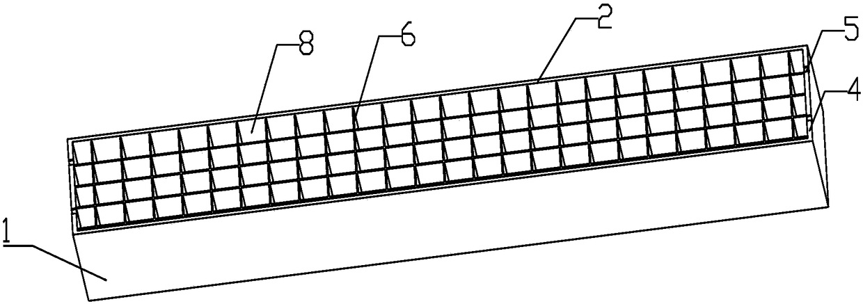
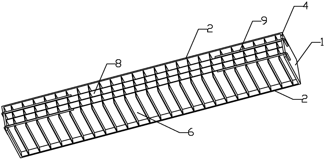
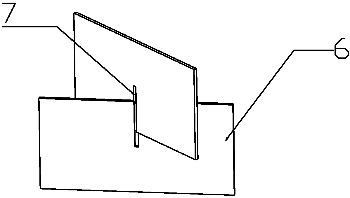
[0013] like figure 1 and 2 As shown, a square multi-cavity steel plate-concrete composite beam includes: a square multi-cavity space steel beam 1 and concrete, and concrete is poured in the square multi-cavity space steel beam 1 to form a combined integral member; wherein: the square multi-cavity space steel beam 1 The beam 1 is composed of a steel plate shell and a steel plate cavity 6 with a cutout 7. The steel plate shell is welded by two long steel plates 2, one bottom steel plate 3 and two short steel plates 4 to form a cuboid structure without a cover. The steel plate cavities 6 of the cutouts 7 are intersected up and down, welded in the steel plate shell to form a square multi-cavity steel beam 1, and concrete is poured in the steel beam 1 to form a square multi-cavity steel plate-concrete composite beam.

[0014] The height of the steel plate cavity 6 is lower than the steel plate shell, and the height difference between the two needs to be greater than the diameter o...


PUM


Abstract

The invention discloses a square multi-cavity steel plate and concrete combination beam, and belongs to the field of constructional engineering. The square multi-cavity steel plate and concrete combination beam includes a multi-cavity space steel beam and concrete. Concrete is poured in the square multi-cavity space steel beam to form a combined entire component, wherein the square multi-cavity space steel beam is composed of a steel plate shell and steel plate cavities provided with incisions. The steel plate shell is made of five steel plates via welding, and the steel plate cavities provided with incisions are inserted up and down and are arranged in the steel plate shell through welding to form the square multi-cavity space steel beam. Concrete is poured in the steel beam to form the square multi-cavity steel plate and concrete combination beam. The problem that a traditional concrete member is prone to crack and expose cracks is overcome. The steel plate cavities have a great horizontal restraining effect on concrete, so that the compression performance and light weight of concrete can be fully developed. The formed combined beam is good in whole performance. The steel plate shell replaces steel bars and section steel in a traditional beam and plays a template function. The construction work of template mounting and dismounting is omitted, and the steel plate shell can replace a traditional template on a construction site. Therefore, the construction progress is accelerated, and the economic benefit is increased.

Description

technical field [0001] The invention belongs to the field of construction engineering, and in particular relates to the field of a square multi-cavity steel plate-concrete composite beam. Background technique [0002] At present, urban viaducts, long-span bridges, industrial and civil buildings, etc. are mainly cast-in-place concrete structures. This construction method has a long construction period, which greatly affects the progress of the project. It brings inconvenience to life, causes environmental pollution, and increases social costs. Moreover, the traditional concrete components commonly used in buildings are heavy and unsuitable for long-span structures; at the same time, the crack resistance is poor, and the cracks are exposed, which reduces the service life of the components. On-site pouring has many construction procedures, requires maintenance, and the construction period is long, and is affected by the construction environment. and climate conditions; traditi...

Claims


Application Information

Patent Timeline
Patent Type & Authority Applications(China)
IPC IPC(8): E04C3/293
CPCE04C3/293
Inventor 李春宝马军李高杰陈玉鹏黄先培马晓嵩王磊
Owner CHINA UNIV OF PETROLEUM (EAST CHINA)
Why Eureka
Try Eureka