Automatic temperature control fan with thermal expansion and contraction principle

A technology of thermal expansion and cold contraction, automatic temperature control, applied in engine control, pump control, machine/engine, etc., can solve the problems of complex structure and high cost, and achieve the effect of simplified structure, simple structure and economical materials

Inactive Publication Date: 2018-08-10
孙佳庆
View PDF0 Cites 8 Cited by
  • Summary
  • Abstract
  • Description
  • Claims
  • Application Information

AI Technical Summary

Problems solved by technology

The structural composition is t

Method used


Image

  • Automatic temperature control fan with thermal expansion and contraction principle
  • Automatic temperature control fan with thermal expansion and contraction principle
  • Automatic temperature control fan with thermal expansion and contraction principle

Examples


Embodiment 1

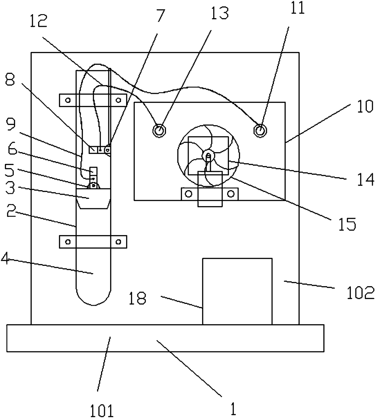
[0022] Embodiment 1: The principle of thermal expansion and cold contraction automatic temperature control fan, (such as figure 1 Shown) has the mounting frame 1 that can be placed on the desktop and is inverted T shape, and described mounting frame 1 has vertical plate 102, and the plate body of described vertical plate 102 is fixedly installed bottle mouth upwards vertical glass test tube 2; The inside of the glass test tube 2 is sealed and fitted with a moving piston 3 that can slide freely up and down along the tube wall in the axial direction and closely fits the tube wall, and the outer circumference of the moving piston 3 and the glass test tube 2 tube wall The surface is coated with lubricating grease; and the closed cavity formed by the sealing of the moving piston 3 in the lower part of the glass test tube 2 is sealed with a gas medium 4 that can push the moving piston 3 to move up and down for a certain distance after thermal expansion and cold contraction; the movin...

Embodiment 2

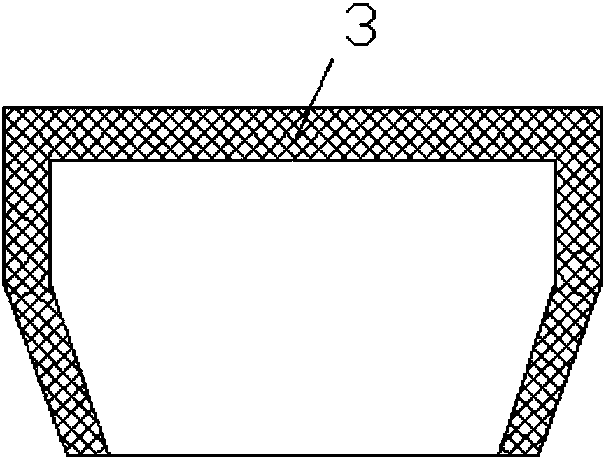
[0023] Embodiment 2: On the basis of the structure of Embodiment 1, in order to reduce the excessive influence of the rising resistance caused by the gravity of the moving piston 3 during the upward movement in the smooth glass test tube 2 by the expanding gas of the moving piston 3; and in combination For the lubricating and sealing effect of grease, select more suitable materials to improve the sealing effect of the moving piston 3 on the sealed gas medium 4 at the bottom of the glass test tube 2: the moving piston 3 is a hollow cover structure, (such as image 3 shown) and made of Styrofoam.

Embodiment 3

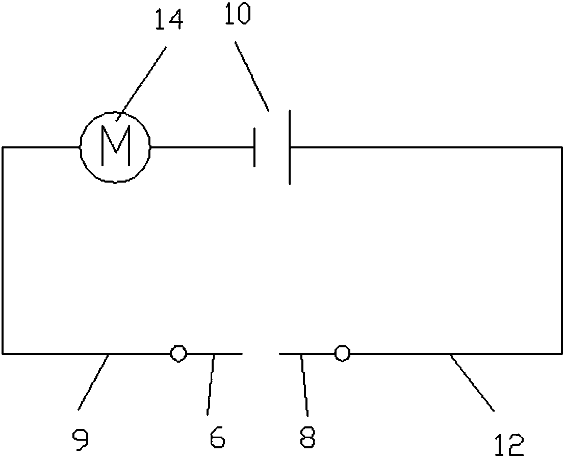
[0024] Embodiment 3: On the basis of the structure of Embodiment 1, as another embodiment of the present invention, in order to achieve a better and more stable connection between the rechargeable battery 10 and the positive and negative metal sheets: the positive and negative electrodes of the rechargeable battery 10 The extreme end is fixedly installed on the positive terminal 11 on the vertical plate 102 through the exposure and is connected to the positive metal sheet 6 through the wire I9; II12 is connected to the negative metal sheet 8 .


PUM


Abstract

The invention provides an automatic temperature control fan with the thermal expansion and contraction principle. The automatic temperature control fan is composed of a mounting frame, a glass test tube, a moving piston, a positive electrode metal sheet, a negative electrode metal sheet, a small direct-current motor, fan impellers, a rechargeable battery and a solar cell panel, wherein lubricatinggrease coats the moving piston, the positive electrode metal sheet moves up and down along with the piston, the position of a fixed negative electrode metal sheet are fixedly arranged on a negative metal sheet mounting frame, the positive electrode metal sheet and fixed negative electrode metal sheet are used as an automatic switch. According to the fan, the property that gas heat expansion and cold contraction is utilized, the moving piston moves up and down, so that the positive electrode metal sheet and the negative electrode metal sheet are enabled to be combined or separated to realize automatic connection or disconnection of the power supply circuit of the small direct-current motor and the design of the automatic temperature-controlled fan; and the structure is simple and economic,the electric energy supply is green and environment-friendly.

Description

technical field [0001] The invention belongs to the technical field of automatic temperature-controlled fans, and in particular relates to an automatic temperature-controlled fan based on the principle of thermal expansion and cold contraction. Background technique [0002] At present, most fans that can realize automatic temperature control are composed of electronic components such as temperature sensors, central controllers, central control chips, relays, and fan motors. Intelligent start-stop control. The structural composition is too complicated and the cost is high. Therefore, a small temperature-controlled fan with simple structure and automatic start-stop control of the fan is proposed by using the principle of gas thermal expansion and cold contraction, so that it is more in line with today's green concept design of energy saving and environmental protection. The following technical solutions are proposed. Contents of the invention [0003] The technical problem...

Claims


Application Information

Patent Timeline
IPC IPC(8): F04D27/00
CPCF04D27/00F05D2270/303
Inventor 常保健孙佳庆
Owner 孙佳庆
Why Eureka
Try Eureka