
Magnetic bearing used for switch reluctance motor

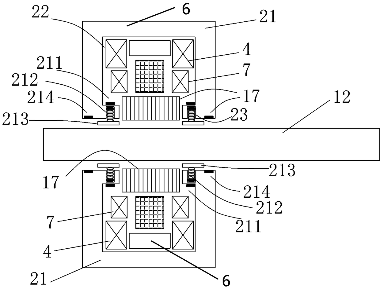
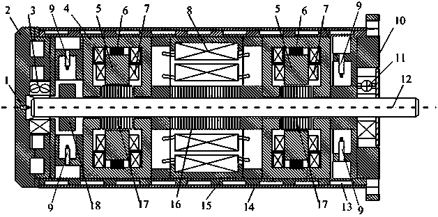
A technology of switched reluctance motor and magnetic suspension bearing, applied in the field of machinery, can solve the problems of large device, affecting accuracy, large load loss, etc., and achieve the effect of eliminating lubrication and cooling device, prolonging the service life of equipment, and safe motor operation.

Pending Publication Date: 2018-08-10
苏州容浦机电科技有限公司
View PDF8 Cites 7 Cited by
  • Summary
  • Abstract
  • Description
  • Claims
  • Application Information

AI Technical Summary

Problems solved by technology

[0003] In the prior art, mechanical wear not only greatly reduces the service life of the switched reluctance servo motor and affects the accuracy, but also causes the uneven air gap of the switched reluctance servo motor, the heating of the winding, and the increase in temperature rise, which deteriorates the characteristics of the motor. The efficiency is reduced, shortening the service life of the switched reluctance motor and equipment, and at the same time, it brings the problem of lubricating fluid and cooling fluid pollution
In order to overcome these problems, new bearings such as air bearings and liquid bearings were widely used in early servo control systems, which reduced the mechanical wear of the bearings. In particular, the liquid floating bearing still pollutes the environment, and its application is limited, which affects the efficiency and service life of the motor.

Method used


Image

  • Magnetic bearing used for switch reluctance motor
  • Magnetic bearing used for switch reluctance motor

Examples


Embodiment Construction

[0018] In order to facilitate the understanding of the present invention, the magnetic suspension bearing will be more fully described below with reference to the relevant drawings. A preferred embodiment of the magnetic suspension bearing is given in the accompanying drawings. However, magnetic suspension bearings can be implemented in many different forms and are not limited to the embodiments described herein. On the contrary, the purpose of providing these embodiments is to make the disclosure of the magnetic suspension bearing more thorough and comprehensive.

[0019] It should be noted that when an element is referred to as being “fixed” to another element, it can be directly on the other element or there can also be an intervening element. When an element is referred to as being "connected to" another element, it can be directly connected to the other element or intervening elements may also be present. In contrast, when an element is referred to as being "directly on...


PUM


Abstract

The invention discloses a magnetic bearing used for a switch reluctance motor. The magnetic bearing comprises a magnetic bearing supporting sleeve, an annular guide groove is formed inside the magnetic bearing supporting sleeve, a magnetic bearing rotor arranged outside a motor rotating shaft in a sleeving manner is arranged in the annular guide groove, a magnetic bearing radial control set is arranged on the outer side of the magnetic bearing rotor, magnetic pieces are arranged at one end of the magnetic bearing radial control set, and the outer sides of the magnetic pieces are each providedwith a magnetic bearing axial control winding and a magnetic bearing radial control winding; and concave grooves are formed in the two sides of a notch where the magnetic bearing and the motor rotating shaft are connected in a sleeving manner, a plurality of elastic elements are arranged in each concave groove, and a radial distance sensor is further arranged on the notch. The magnetic bearing issmall in friction loss and high in working efficiency, the rotor floats on the space through magnetic field force, the bearing supporting performance is good, the rotating shaft is prevented from being collided, and the radial sensor monitoring function is achieved.

Description

technical field [0001] The invention relates to the technical field of machinery, in particular to a magnetic suspension bearing used for a switched reluctance motor. Background technique [0002] With the substantial improvement of domestic motor manufacturing level, AC servo motor control technology has gradually been mastered by more and more domestic manufacturers, which has contributed to the realization of domestic servo drive manufacturers from start to full expansion in less than ten years. development trend. Motor and drive companies have devoted themselves to the servo industry and realized industrialization and large-scale production. However, the domestic servo motor mechanical bearing control system is mainly low-end products with low power, and the high cost performance attracts the use of relatively low accuracy requirements. Customers still have a large gap with foreign products in terms of function, performance and technology. The AC servo motor control syst...

Claims


Application Information

Patent Timeline
Patent Type & Authority Applications(China)
IPC IPC(8): F16C32/04
CPCF16C32/0406F16C2380/26
Inventor 王博
Owner 苏州容浦机电科技有限公司
Learn More