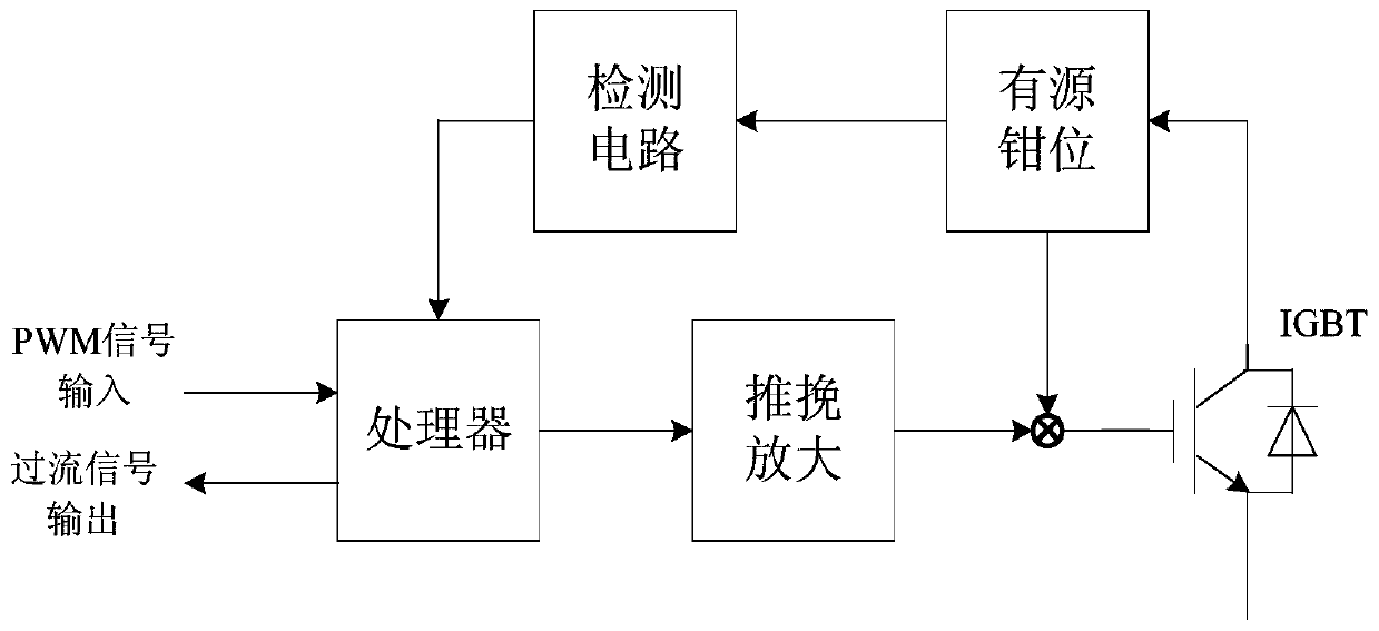
An IGBT overcurrent detection device and method based on an active clamp feedback type
An overcurrent detection and detection circuit technology, applied in the direction of measurement device, measurement of electrical variables, bipolar transistor testing, etc., can solve problems affecting system reliability, detection time delay, heat loss, etc., and achieve easy fault analysis and detection. Comprehensive and reliable effect
- Summary
- Abstract
- Description
- Claims
- Application Information
AI Technical Summary
Problems solved by technology
Method used
Image
Examples
Embodiment 1
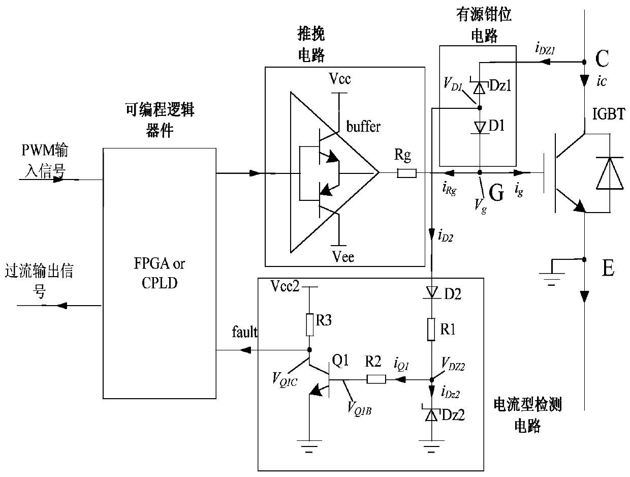
[0031] Embodiment 1: The detection circuit of this embodiment is based on a current signal, and the current detection circuit is composed of 3 resistors, 2 diodes and 1 triode. Such as figure 2 The anode of the shown diode D2 is connected to the anode of D1 in the active clamp circuit, the cathode of the diode D2 is connected to one end of the resistor R1, the other end of the resistor R1 is connected to the cathode of the Zener diode Dz2, and the anode of the Zener diode Dz2 is connected to the reference ground . At the same time, the cathode of the regulator diode Dz2 is connected to one end of the resistor R2, the other end of the resistor R2 is connected to the base of the transistor Q1, the emitter of the transistor Q1 is grounded, one end of the collector of the transistor Q1 is connected to one end of the resistor R3, and the other end of the resistor R3 One end is connected to the power supply Vcc2. The collector of the transistor Q1 is connected to the input port o...
Embodiment 2
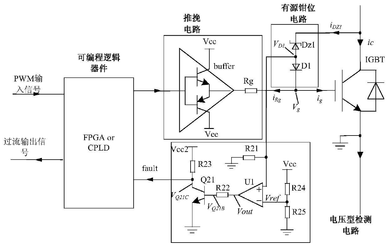
[0037] Embodiment 2: The detection circuit of this embodiment is based on a voltage signal, and the working principle of other circuits is the same as that of Embodiment 1. The voltage detection circuit is composed of 5 resistors, 1 comparator and 1 triode. The positive input terminal of the comparator U1 is respectively connected to one end of the resistor R21 and the anode of the diode D1 in the active clamping circuit; the other end of the resistor R21 is grounded, and the comparison The reverse input terminal of the comparator U1 is respectively connected to one end of the resistors R24 and R25; the other end of the resistor R24 is connected to the power supply Vcc2, and the other end of the resistor R25 is grounded; the output terminal of the comparator U1 is connected to the resistor R22; the other end of the resistor R22 is connected to the transistor Q21 The base and the emitter of the transistor Q21 are grounded, and one end of the collector of the transistor Q21 is ...
Embodiment 3
[0042] Embodiment 3: Corresponding to Embodiment 1 and 2, this embodiment also provides an IGBT overcurrent detection method based on active clamp feedback type, which mainly includes:
[0043] When the IGBT is over-current, that is, when the voltage across the IGBT exceeds the breakdown voltage of the active clamp diode, the active clamp circuit works to clamp the IGBT at the protection voltage; the detection circuit effectively extracts the active clamp action The time when the TVS branch current flows or the time when the clamping voltage exists, and the time signal is transmitted to the processor circuit; the processor counts and counts the time and times of the signal transmitted by the detection circuit; when the processor circuit receives When the time signal of the current flowing through the TVS branch or the time signal of the clamp voltage exceeds the system setting time, it can be determined that the IGBT has an overcurrent fault.
[0044] Among them, the system se...
PUM
 Abstract
Description
Claims
Application Information
 - R&D
- Intellectual Property
- Life Sciences
- Materials
- Tech Scout
- Unparalleled Data Quality
- Higher Quality Content
- 60% Fewer Hallucinations
Browse by: Latest US Patents, China's latest patents, Technical Efficacy Thesaurus, Application Domain, Technology Topic, Popular Technical Reports.
© 2025 PatSnap. All rights reserved.Legal|Privacy policy|Modern Slavery Act Transparency Statement|Sitemap|About US| Contact US: help@patsnap.com


