Layer-stranded strip-shaped optical cable

A ribbon optical cable and layer-stranded technology, applied in the field of layer-stranded ribbon optical cable, can solve the problems of optical cable burning in case of fire, secondary environmental pollution, difficulty in personnel escaping, etc., and achieve bending resistance and tensile resistance. Improved performance, high reliability, increased tensile properties

Pending Publication Date: 2018-08-10
SHAANXI SCI TECH UNIV
View PDF2 Cites 1 Cited by
  • Summary
  • Abstract
  • Description
  • Claims
  • Application Information

AI Technical Summary

Problems solved by technology

Therefore, in order to ensure the reliable operation of communication equipment and networks in places requiring low-smoke, halogen-free flame retardant, it is necessary to effectively solve the fire hazards caused by the burning and dripping of optical cables in case of fire, and the fact that optical cables are prone to release a large amount of black in a burning fire. Thick smoke and toxic gases cause secondary environmental pollution and difficulty in escaping

Method used


Image

  • Layer-stranded strip-shaped optical cable
  • Layer-stranded strip-shaped optical cable
  • Layer-stranded strip-shaped optical cable

Examples


Embodiment 1

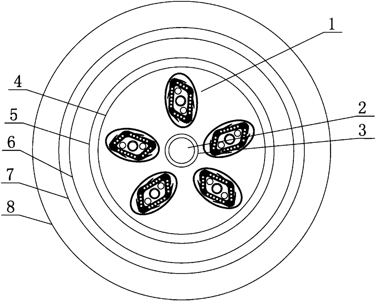
[0037] like figure 1 As shown, the present invention provides a layer-stranded ribbon optical cable, which includes an optical fiber part 1 and a metal strengthening core 2. There are five optical fiber parts 1, and the five optical fiber parts 1 are evenly distributed in the insulating layer 4. The metal reinforcing core 2 is set in the middle of the insulating layer 4, the insulating layer 4 is provided with a water blocking layer 5, the water blocking layer 5 is provided with an inner sheath 6, the inner sheath 6 is provided with a reinforcing layer 7, and the reinforcing layer 7 is provided with an outer sheath 8. The reinforcing layer 7 is made of aramid yarn.

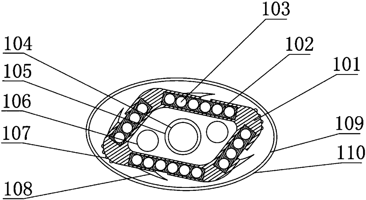
[0038] like image 3As shown, the optical fiber portion 1 includes an accommodating portion 101 and an optical fiber ribbon 103 . The accommodating portion 101 is a rhombus-shaped frame body. The inner cavity of the rhombus-shaped frame is provided with a metal reinforcing core 104 and a filling rope 106 , and a ...

Embodiment 2

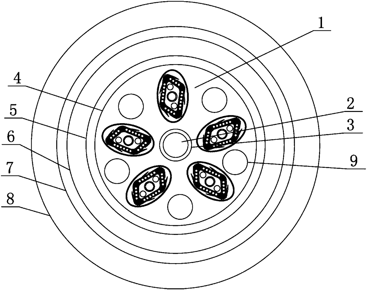
[0044] like figure 2 As shown, the difference between this embodiment and Embodiment 1 is that a filling rope 9 is arranged between each optical fiber part 1 to reduce the gap between each optical fiber part 1, and the filling rope 9 also plays a protective role at the same time. Steel wire reinforcing cores can also be arranged between each optical fiber portion 1 to improve the structural strength of the entire optical fiber cable.

Embodiment 3

[0046] A flame retardant ointment, comprising the components by mass: 78 parts of base oil, 9 parts of composite thickener, 0.8 part of flame retardant, and 0.5 part of antioxidant.

[0047] Described base oil is hydrogenated paraffin base oil / hydrogenated naphthenic oil mixed oil, and mass ratio is 2:3; Described composite thickener is polyacrylamide / fatty alcohol polyoxyethylene ether, and mass ratio is 5: 7; the flame retardant is triallyl isocyanurate and nano-tin powder, and the mass ratio is 90:0.15, wherein triallyl isocyanurate is a thermal crosslinking agent, and nano-tin powder is a catalyst ; Antioxidant is tert-butyl hydroquinone.

[0048] Example 1 Flame retardant performance table of flame retardant ointment:

[0049]

[0050]


PUM


Abstract

The invention discloses a layer-stranded strip-shaped optical cable. The layer-stranded strip-shaped optical cable comprises five optical fiber parts and a first metal reinforcing core, the optical fiber parts are uniformly distributed in an insulating layer, and the first metal reinforcing core is arranged in the middle of the insulating layer; a water stopping layer is arranged outside the insulating layer, an inner sheath is arranged outside the water stopping layer, a reinforcing layer is arranged outside the inner sheath, and an outer sheath is arranged outside the reinforcing layer; eachoptical fiber part comprises an accommodating part and an optical fiber belt, an insulating inner layer covers the periphery of each optical fiber belt, the optical belts are arranged in rectangulargrooves, filling layers are arranged among the rectangular grooves and the optical fiber belts, shielding layers are arranged outside the rectangular grooves, and reinforcing cores are arranged amongthe rectangular grooves and the shielding layers. The layer-stranded strip-shaped optical cable has good stretch resistance, water resistance, a good fire retardant effect, a large transmission capacity, a high speed, and good interference resistance, and is suitable for an occasion in which a large-scale network is built.

Description

technical field [0001] The invention relates to an optical fiber cable, in particular to a layer twisted ribbon optical cable. Background technique [0002] Optical fiber communication has been widely used due to its advantages of large information capacity, good confidentiality, light weight, small size, and long distance without repeaters. Broader and deeper levels of development. The application of optical fiber is bringing profound impact and changes to human life. The existing optical fiber cables have insufficient strength and tensile strength, and there are hidden dangers of breaking during the winding process and at both ends of the cable. Their functions are single, and there is a lot of inconvenience in the current signal transmission process. It needs to be equipped with both optical and electrical cables, but the optical fiber is usually not resistant to bending, which will cause the optical fiber to break. [0003] The invention patent with the publication nu...

Claims


Application Information

Patent Timeline
IPC IPC(8): G02B6/44
CPCG02B6/4403G02B6/443G02B6/4432G02B6/4436G02B6/44384
Inventor 陈正涛
Owner SHAANXI SCI TECH UNIV
Why Eureka
Try Eureka