Single-mode driven dual-driving-feet n-shaped linear ultrasonic motor and control method thereof
A linear ultrasonic motor, dual-drive technology, applied in the direction of generator/motor, piezoelectric effect/electrostrictive or magnetostrictive motor, electrical components, etc. Operating frequency bandwidth, high space utilization, compact structure
- Summary
- Abstract
- Description
- Claims
- Application Information
AI Technical Summary
Problems solved by technology
Method used
Image
Examples
Embodiment 1
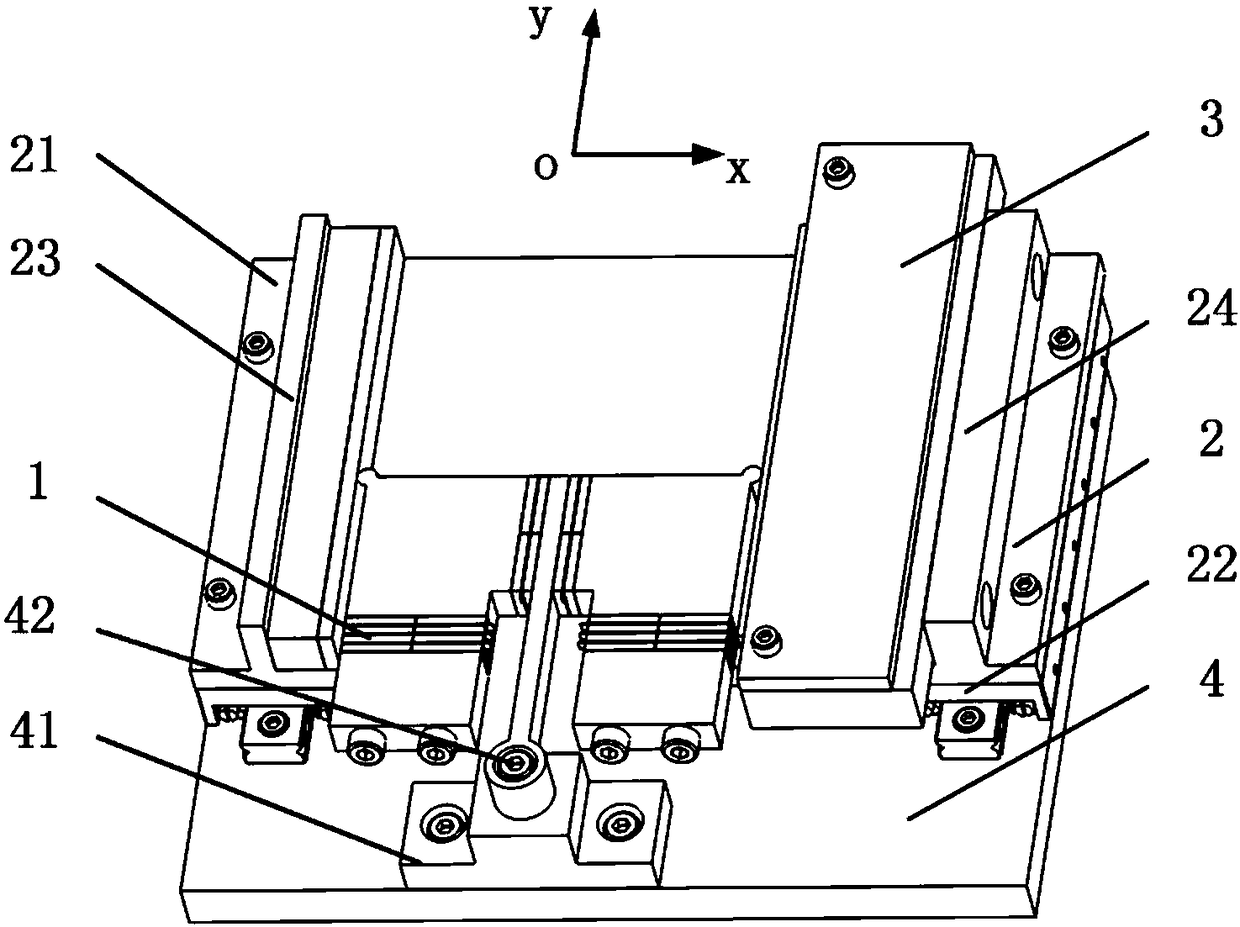
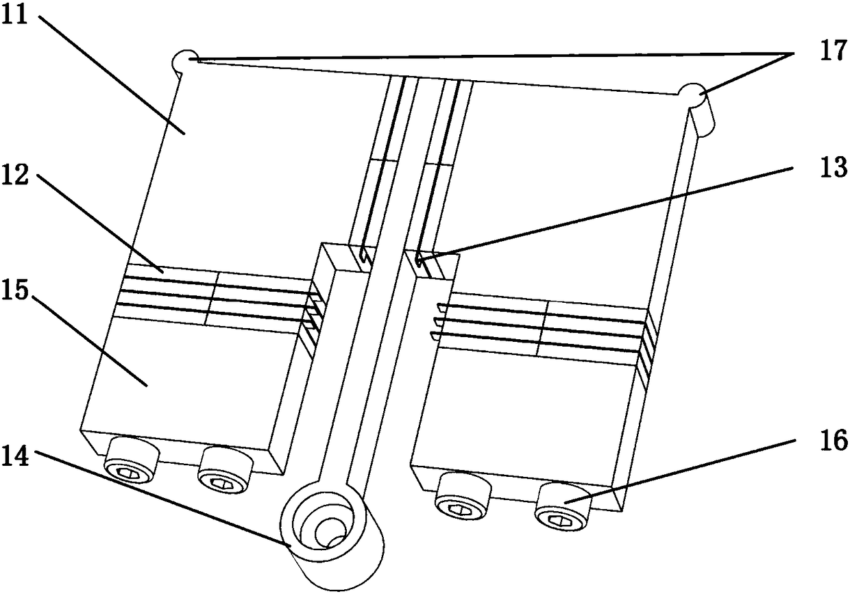
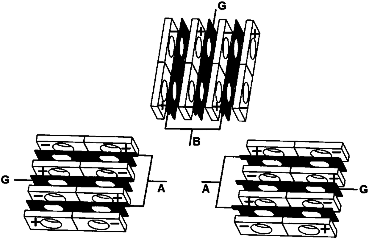
[0041] A single-mode driven double-drive foot-shaped linear ultrasonic motor designed by the present invention is as follows: figure 1 shown. It includes a stator 1, a mover 2, a pre-pressure applying device 3 and a base 4. Specifically, a pillar 41 is arranged on the base 4 to support the stator 1 and keep the stator 1 suspended in the air during operation, so as to keep the stator 1 and the mover 2 in contact only at the driving foot. The mover is formed by connecting two guide rails 22 through a platform 21. Two ridges 23, 24 are arranged on the platform, one of which 23 is pasted with a friction ceramic sheet, and is in contact with the driving foot on one side of the stator, and the other ridge The strip 24 is used to fix the prestressing device 3 . The pre-pressure device 3 is used to apply a pre-pressure between the stator 1 and the mover 2, and paste the friction ceramic sheet to contact with the other driving foot of the stator 1. When the preloading device 3 exert...
Embodiment 2
[0048] The difference between this embodiment and Embodiment 1 lies in that the structure of the pre-pressure applying device is different. Figure 7 Shown is a schematic structural diagram of the second pre-pressure applying device of a single-mode-driven double-drive foot-shaped linear ultrasonic motor. It includes a hinge support 35 , a preload spring 36 , a force applying bolt 37 and a force applying hole 38 . Wherein, the hinge support 35 is hinged on the mover 2 by a bolt, and a friction ceramic sheet is pasted on the side close to the stator to contact the driving foot 17 . The force application hole 38 is a threaded hole located on the mover 2, and is far enough away from the hinge point. The threaded side of the force applying bolt 37 has a large radius and is matched with the force applying hole 38 ; the non-threaded side has a small radius and can pass through the pre-compression spring 36 against the hinge support 35 . When the force applying bolt 37 is tightened...
PUM
 Abstract
Description
Claims
Application Information
 - R&D
- Intellectual Property
- Life Sciences
- Materials
- Tech Scout
- Unparalleled Data Quality
- Higher Quality Content
- 60% Fewer Hallucinations
Browse by: Latest US Patents, China's latest patents, Technical Efficacy Thesaurus, Application Domain, Technology Topic, Popular Technical Reports.
© 2025 PatSnap. All rights reserved.Legal|Privacy policy|Modern Slavery Act Transparency Statement|Sitemap|About US| Contact US: help@patsnap.com


