
Method for cleaning petrochemical engineering pipeline with ice slurry

A technology of petrochemical and ice slurry, which is applied in the field of cleaning petrochemical pipelines with ice slurry, which can solve the problems of low pigging efficiency, high pipeline risk, and heavy manual cleaning workload, etc., and achieves the effect of high cleaning efficiency and simple operation process

Pending Publication Date: 2018-08-14
广州中臣埃普科技有限公司
View PDF6 Cites 2 Cited by
  • Summary
  • Abstract
  • Description
  • Claims
  • Application Information

AI Technical Summary

Problems solved by technology

(Limitations: inefficient, consume a lot of water, used for short distances, incomplete cleaning, long working hours)
[0005] Mechanical cleaning: including robots and manual cleaning, that is, using manual methods to excavate pipelines to remove dirt (limitations: manual cleaning workload is large, work efficiency is low, cleaning is not thorough, and even pipelines are damaged); PIG pig cleaning (limitations : The pig can’t move through the valve and variable diameter of the pipeline, and it is easy to get stuck at the elbow and weld. It usually takes multiple times to clean the residue inside the pipe. The pigging efficiency is low, the cleaning is not thorough, and the risk of PIG blocking the pipeline High, when the blockage is serious, the pipeline needs to be excavated, which is very destructive to the pipeline and the ground)
[0006] Chemical cleaning: Put the chemical solution into the pipeline, and the chemical will react with the pipeline dirt and decompose, so as to flow out of the pipeline with the solution to achieve the purpose of cleaning (limitations: easy to corrode the pipeline, residual chemical cleaning agent, causing damage to the pipeline and water quality) Pollution, and the chemical aqueous solution after cleaning is difficult and expensive to deal with, causing re-pollution and damage to the environment)
[0007] The above-mentioned cleaning methods all have their own defects, and have limitations when cleaning the inside of the pipeline

Method used

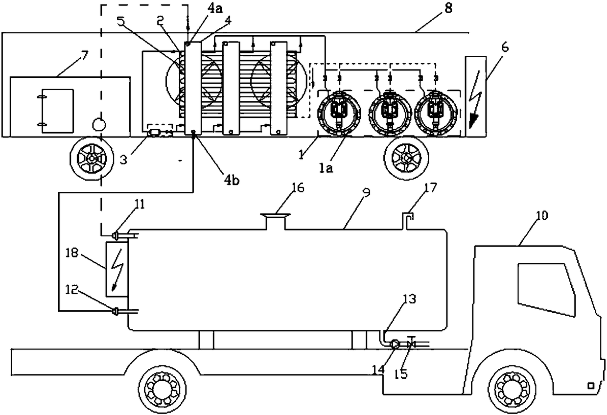
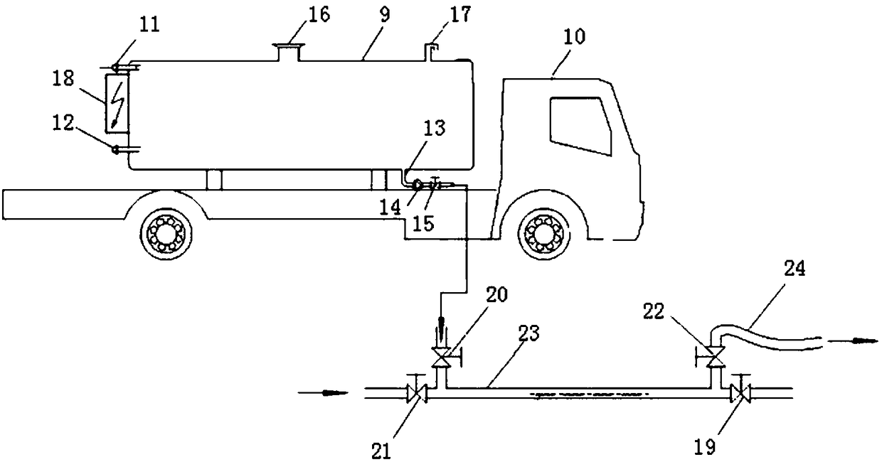

Image

  • Method for cleaning petrochemical engineering pipeline with ice slurry
  • Method for cleaning petrochemical engineering pipeline with ice slurry
  • Method for cleaning petrochemical engineering pipeline with ice slurry

Examples


Embodiment Construction

[0035] The following are specific embodiments of the present invention and in conjunction with the accompanying drawings, further describe the technical solution of the present invention, but the present invention is not limited to these embodiments.

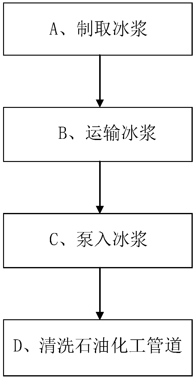
[0036] Such as figure 1 Shown, adopt the method for ice slurry cleaning petrochemical pipeline to comprise the steps:

[0037] A. Preparation of ice slurry: the ice slurry production unit and ice slurry storage unit produce high-concentration ice slurry during non-operating hours;

[0038] B. Transport the prepared ice slurry storage unit to the petrochemical pipeline to be cleaned;

[0039] C. The high-concentration ice slurry is injected into the petrochemical pipeline 23 to be cleaned from the valve interface of the petrochemical pipeline 23 by using the ice slurry delivery pump 14, so that the high-concentration ice slurry forms a solid-like icicle in the petrochemical pipeline 23 and have liquidity;

[0040] D. Use the p...


PUM


Abstract

The invention provides a method for cleaning a petrochemical engineering pipeline with ice slurry, and belongs to the technical field of pipeline cleaning methods. The cleaning method includes the steps that A, the ice slurry is prepared, specifically, an ice slurry preparing unit and an ice slurry storing unit are used for preparing the ice slurry in non-working time; B, the ice slurry storing unit containing the prepared ice slurry is conveyed to the to-be-cleaned petrochemical engineering pipeline; C, the high-concentration ice slurry is injected into the to-be-cleaned petrochemical engineering pipeline from a valve port of the petrochemical engineering pipeline by utilizing an ice slurry conveying pump, and the high-concentration ice slurry forms a solid-like ice column in the petrochemical engineering pipeline and has flowability; and D, the high-concentration ice slurry is pushed to flow through the petrochemical engineering pipeline by pressure or power of the ice slurry conveying pump or original fluid in the pipeline, so that the cleaning purpose is achieved. The cleaning method is adopted for cleaning the interior of the pipeline with the ice slurry, no chemical agent isused, and the method is environmentally friendly and safe.

Description

technical field [0001] The invention belongs to the technical field of pipeline cleaning methods, and relates to a method for cleaning petrochemical pipelines with ice slurry. Background technique [0002] Petrochemical pipelines, including oil wells, petroleum pipelines, submarine pipelines, oil field water injection pipelines, chemical fluid pipelines, natural gas pipelines, hot water pipelines, steam pipelines, large heat exchange equipment pipelines, tubular heating furnaces, power plant ash pipelines, petrochemical processing When various pipelines such as factories are installed and put into use, there will be impurities and other dirt residues on the inner wall of the pipeline and the joints during the installation process. When the pipeline is used for a long time, there will be dirt, sediment and other residues attached to the inner wall of the pipeline, which will affect the purity and quality requirements of the fluid in the pipeline, reduce the delivery flow of t...

Claims


Application Information

Patent Timeline
Patent Type & Authority Applications(China)
IPC IPC(8): B08B9/032B08B13/00
CPCB08B9/027B08B9/032B08B9/0321B08B9/057B08B13/00E03B7/006E03F9/00
Inventor 何远娜胡宏伟吴积涛
Owner 广州中臣埃普科技有限公司
Learn More