Aluminum alloy laser-TIG composite additive manufacturing method

An additive manufacturing, aluminum alloy technology, applied in the field of aluminum alloy laser-TIG composite additive manufacturing, can solve the problems of reducing laser energy absorption, affecting the accuracy of thin-walled structures, unfused or slag inclusion, etc., and improving porosity defects. problems, improve the bonding performance between layers, and improve the effect of severe deformation

Active Publication Date: 2018-08-14
DALIAN UNIV OF TECH
View PDF10 Cites 13 Cited by
  • Summary
  • Abstract
  • Description
  • Claims
  • Application Information

AI Technical Summary

Problems solved by technology

[0003] At present, metal additive manufacturing technology using laser as a single heat source is widely used in various fields, but aluminum alloy laser additive manufacturing has certain defects.
On the one hand, the reflectivity of aluminum alloy to laser is extremely high, which reduces the absorption of laser energy during the forming process; The rate is low, the problem of polluting the environment
[0004] The additive manufacturing technology using the arc as the single heat source is also one of the metal additive methods, but due to the high thermal conductivity of the aluminum alloy, more energy is absorbed during the arc additive manufacturing, resulting in serious heat accumulation, resulting in relatively high Large deformation affects the accuracy of thin-walled (single-channel and multi-layer) structures
[0005] Chinese patent CN 107283061 A discloses a laser-CMT welding aluminum alloy additive manufacturing method and forming system. This method uses laser and electric arc as a composite heat source, and an induction coil as a preheating device. Additive manufacturing of aluminum alloy components; but in this method, the CMT process is prone to defects such as unfused or slag inclusions during the multi-layer additive process

Method used


Image

  • Aluminum alloy laser-TIG composite additive manufacturing method

Examples


Embodiment Construction

[0021] The specific implementation manner of the present invention will be further described below in conjunction with the accompanying drawings.

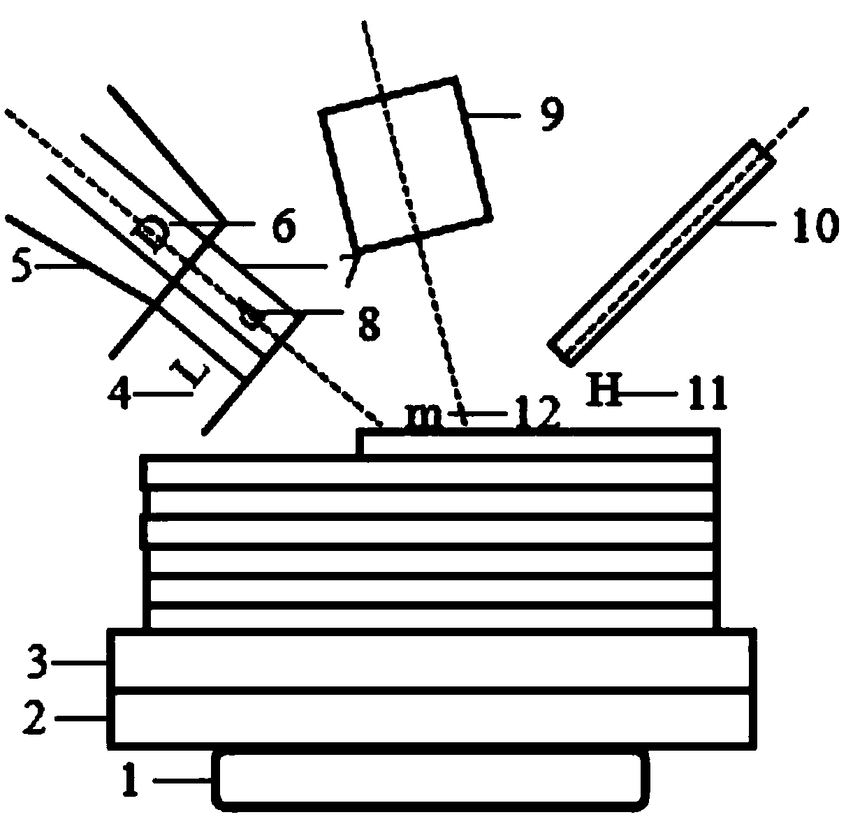
[0022] An aluminum alloy laser-TIG composite additive manufacturing method, using fixtures to fix the preheating device 2 above the steering table 1, and fixing the substrate 3 above the preheating device 2, the angle between the wire feed nozzle 5 and the horizontal direction is 25° , the angle between the laser head 9 and the vertical direction is 10°, the angle between the welding torch 10 and the vertical direction is 50°, and the manufacturing method includes the following steps:

[0023] S1: The front wire feeding method is adopted. The wire material 7 chooses aluminum alloy 4043 with a diameter d8 of 1.2mm, and the base plate 3 chooses a 20mm thick aluminum alloy 6061; The wire spacing m is 10mm, the tungsten electrode height H11 is 1.5mm; the substrate 3 is preheated, and the preheating temperature is 300°C;

[0024] S2: D...


PUM

PropertyMeasurementUnit
diameteraaaaaaaaaa

Abstract

The invention belongs to the technical field of metal additive manufacturing, and provides an aluminum alloy laser-TIG composite additive manufacturing method. According to the composite additive manufacturing method, a laser and an electric arc are used as composite heat sources, and a TIG mode is adopted, so that additive manufacturing forming of the aluminum alloy thin-wall type (single-channelmulti-layer) structure is realized. The method comprises the following steps of S1, determining the relative position relation among the laser, the electric arc and a wire, and carrying out base plate preheating treatment; S2, forming aluminum alloy laser-TIG composite additive single-channel single-layer structure; and S3-S5, forming aluminum alloy laser-TIG composite additive thin-wall type (single-channel multi-layer) structure. According to the composite additive manufacturing method, the defects that formation is not easy when the laser is used as a single heat source due to the fact that the reflectivity of the aluminum alloy is high, and deformation is serious and the forming quality is poor when the electric arc is used as a single heat source due to the fact that the heat input quantity is high are overcome; and the method is suitable for additive manufacturing of aluminum alloy thin-wall type (single-channel multi-layer) structure and can effectively inhibit air hole defects.

Description

technical field [0001] The invention belongs to the technical field of metal additive manufacturing, and relates to an aluminum alloy laser-TIG composite additive manufacturing method. Background technique [0002] With the development of science and technology and the demand for popularization and application, additive manufacturing technology is rapidly changing the traditional production method. Additive manufacturing technology is a "bottom-up" manufacturing method through material accumulation, which can control and freely add materials, effectively making up for the traditional manufacturing technology that cannot realize complex structure manufacturing, long cycle, high cost, and serious waste of materials. Defects. Aluminum alloy has low density, high strength, good plasticity, excellent electrical conductivity, thermal conductivity and corrosion resistance. The temperature gradient is relatively small during the rapid melting process, and the formed parts are not e...

Claims


Application Information

Patent Timeline
Patent Type & Authority Applications(China)
IPC IPC(8): B23K26/348B23K103/10
Inventor 吴东江刘妙然苗秋玉马广义于京令柴东升
Owner DALIAN UNIV OF TECH
Why Eureka
Try Eureka