Valveless electromagnetic micro pump and manufacturing method thereof

An electromagnetic and micro-pump technology, applied in biochemical equipment and methods, pumps, pump components, etc., can solve the problem that micro-pump technology is difficult to achieve portability, and achieve the effect of miniaturized packaging, small size, and enhanced portability

Active Publication Date: 2018-08-14
SHENZHEN GRADUATE SCHOOL TSINGHUA UNIV
View PDF10 Cites 9 Cited by
  • Summary
  • Abstract
  • Description
  • Claims
  • Application Information

AI Technical Summary

Problems solved by technology

[0006] The main purpose of the present invention is to provide a valveless electromagnetic micropump and its manufacturing method in view of the deficiencies in the prior art, so as to solve the problems that the existing micropump technology is difficult to achieve portability and the like.

Method used


Image

  • Valveless electromagnetic micro pump and manufacturing method thereof
  • Valveless electromagnetic micro pump and manufacturing method thereof
  • Valveless electromagnetic micro pump and manufacturing method thereof

Examples


Embodiment 1

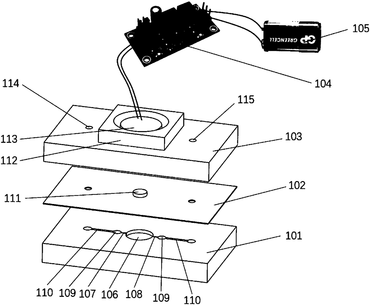
[0059] refer to Figure 1 to Figure 6 , a valveless electromagnetic micropump for two-organ co-culture chip, which consists of a pump body and a power supply system. The power system includes a signal generating module 104 and a battery 105 . The pump body is composed of a pump chamber layer 101 , a film layer 102 and a coil layer 103 in a three-layer structure from bottom to top.

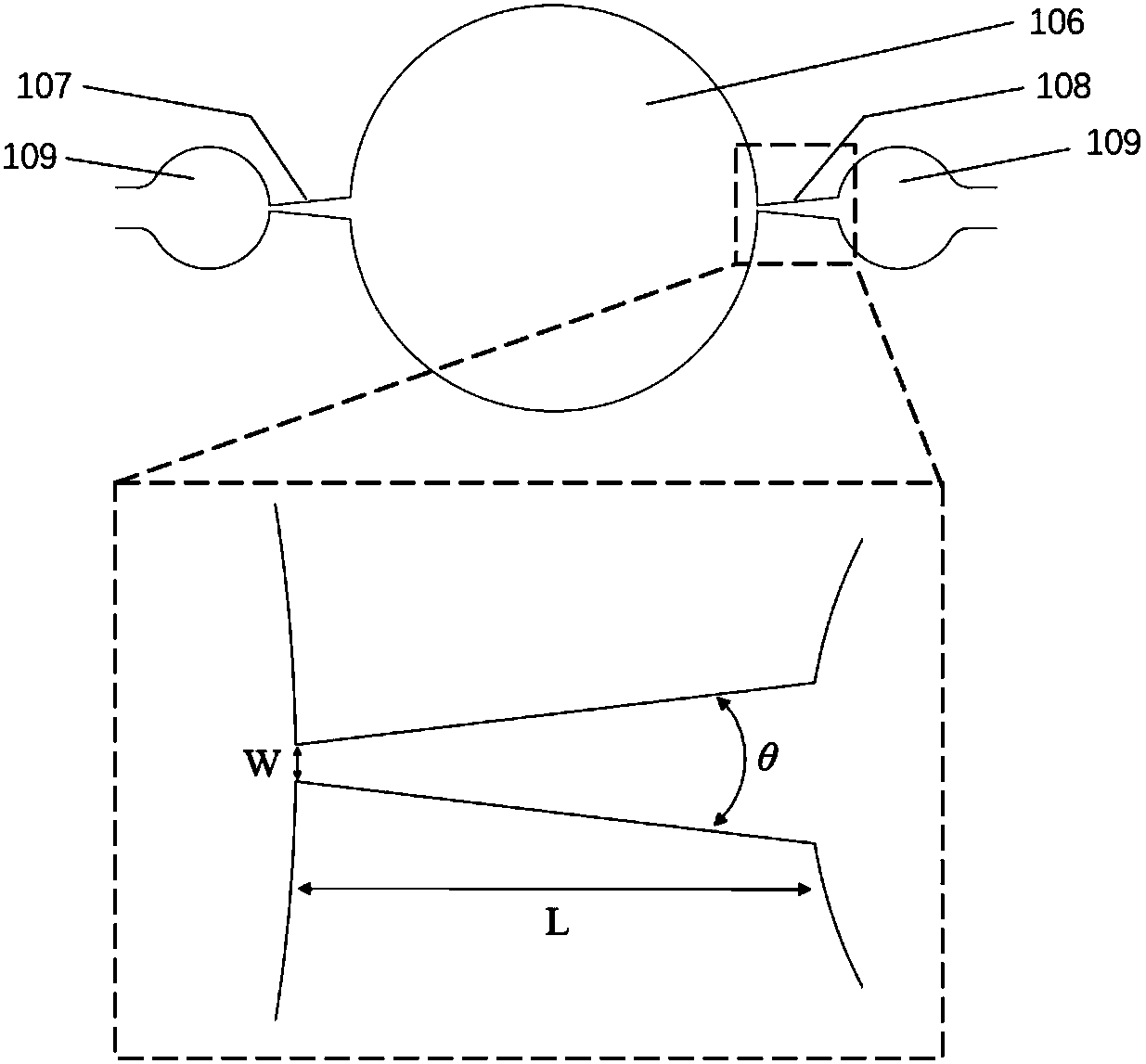
[0060] The structure of the pump cavity layer 101 includes a pump cavity 106 , a first expansion and contraction tube 107 , a second expansion and contraction tube 108 , a buffer cavity 109 , a microchannel 110 and an organ model cavity 601 . The pump chamber 106 is connected to the buffer chambers 109 on both sides through the first expansion and contraction tube 107 and the second expansion and contraction tube 108. The buffer chambers 109 on both sides are respectively connected to the micro-channels 110 on both sides. An organ model cavity 601 forms a loop.

[0061] The first expansion and c...

Embodiment 2

[0075] refer to Figure 1 to Figure 4 , Figure 7 to Figure 8 , a series-parallel model of a valveless electromagnetic micropump consisting of a pump body and a power system. The power system includes a signal generating module 104 and a battery 105 . The pump body is composed of a pump chamber layer 101 , a film layer 102 and a coil layer 103 in a three-layer structure from bottom to top.

[0076] The pump chamber layer 101 structure includes micropump A801, micropump B802, micropump C803, main channel 806, branch channel A804 and branch channel 805. Each micropump includes a pump cavity 106 , a first expansion-contraction tube 107 , a second expansion-contraction tube 108 and a buffer cavity 109 . The pump chamber 106 is connected to the buffer chambers 109 on both sides through the first expansion and contraction tube 107 and the second expansion and contraction tube 108. The buffer chambers 109 on both sides of the micropump A801 ​​are connected to the branch channel A8...


PUM

PropertyMeasurementUnit
diameteraaaaaaaaaa
depthaaaaaaaaaa
thicknessaaaaaaaaaa

Abstract

The invention discloses a valveless electromagnetic micro pump and a manufacturing method thereof. The micro pump comprises a pump body and a power source system; the pump body comprises a pump cavitylayer, a thin film layer and a coil layer which are sequentially stacked from bottom to top; the coil layer comprises an electromagnetic coil; the thin film layer comprises a thin film with a magnet;the power source system supplies power for the electromagnetic coil and generates a changing magnetic field; and due to the mutual effects between the changing magnetic field and the magnet, the magnet is made to drive the thin film to vibrate in a reciprocating manner, and therefore pumping of fluid in the pump cavity layer is driven. The micro pump is small in volume and simple in structure, can be integrated on an organ chip and can solve the problems that an existing organ chip system depends on an external device and is poor in portability.

Description

technical field [0001] The invention relates to the technical field of microfluidics and micromanufacturing, in particular to a valveless electromagnetic micropump and a manufacturing method thereof. Background technique [0002] Organ-on-a-chip is a bionic system that can simulate the main functions of human organs on a microfluidic chip using micro-processing technology. It is a bionic, efficient, and energy-saving tool for physiological research and drug development. In addition to the characteristics of miniaturization, integration, and low consumption of microfluidic technology, organ chip technology can also precisely control multiple system parameters, thereby simulating the complex structure, microenvironment, and physiological functions of human organs. [0003] In order to more realistically simulate the physiological environment in the human body, organ-on-a-chip usually needs to be perfused with a micropump to achieve dynamic cell culture. The flow of fluid will...

Claims


Application Information

Patent Timeline
Patent Type & Authority Applications(China)
IPC IPC(8): F04B43/08F04B43/09F04B53/00C12M3/00
CPCC12M3/00F04B43/086F04B43/088F04B43/09F04B53/00
Inventor 弥胜利孙伟蒲海涛
Owner SHENZHEN GRADUATE SCHOOL TSINGHUA UNIV
Why Eureka
Try Eureka