Battery temperature control device for charging and replacing power station, and electric vehicle charging and replacing power station

A charging and swapping station, battery temperature technology, applied in the direction of battery temperature control, battery/fuel cell control device, electric vehicle charging technology, etc., can solve the problems of normal operation impact, increased operation burden, and untimely recovery of water cooling system, etc., to achieve Meet heat dissipation requirements, save space and manufacturing costs, and meet the effects of diversity

Inactive Publication Date: 2018-08-14
NIO ANHUI HLDG CO LTD
View PDF7 Cites 6 Cited by
  • Summary
  • Abstract
  • Description
  • Claims
  • Application Information

AI Technical Summary

Problems solved by technology

[0004] (1) The display screen of the existing water-cooling system is placed on the unit of the water-cooling system, and the equipment that blocks the display screen cannot be placed in front of the control screen, which limits the flexibility of the design and layout of the charging and swapping station
[0005] (2) Circuit breakers, relays and other components are usually installed inside the water-cooled unit. When the water-cooled unit fails and needs to be powered off in time, or manually restored, it will affect the normal operation of other equipment in the charging station
[0008] B...

Method used


Image

  • Battery temperature control device for charging and replacing power station, and electric vehicle charging and replacing power station
  • Battery temperature control device for charging and replacing power station, and electric vehicle charging and replacing power station
  • Battery temperature control device for charging and replacing power station, and electric vehicle charging and replacing power station

Examples


Embodiment Construction

[0063] In order to further explain the technical means and effects of the present invention to achieve the intended purpose of the invention, a battery temperature control device for charging and swapping stations and an electric vehicle proposed according to the present invention will be described below in conjunction with the accompanying drawings and preferred embodiments. The specific implementation of the charging and swapping station and its functions will be described in detail.

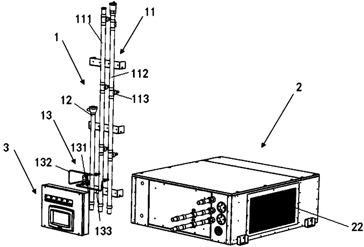
[0064] Such as figure 1 As shown, the present invention provides an embodiment to provide a battery temperature control device for charging and swapping stations, including: a pipeline part 1, a liquid cooling unit 2 and a control part 3, wherein the pipeline part 1 is connected to the charging One or more batteries in the power station are used to provide refrigerant for the batteries to heat or cool the batteries; the liquid cooling unit 2 is connected to the pipeline part 1. As an example, ...


PUM


Abstract

The invention relates to a battery temperature control device for a charging and replacing power station, and an electric vehicle charging and replacing power station. The battery temperature controldevice comprises: a pipeline portion, a liquid cooling machine unit and a control portion, wherein the pipeline portion is connected to one or more batteries of the charging and replacing power station and is used for providing a refrigerant for the batteries to heat or cool the batteries; the liquid cooling machine unit is connected with the pipeline portion and is used for cooling or heating therefrigerant provided for the pipeline portion; and the control portion is connected with the liquid cooling machine unit and is used for controlling the liquid cooling machine unit and the pipeline portion. The charging and replacing power station comprises one or more battery temperature control devices, and the battery temperature control device is arranged in a battery compartment in the electric vehicle charging and replacing station. The pipeline portion, the liquid cooling machine unit and the control portion all adopt a split design, the length of a cable or a hose can be adjusted according to specific space layout requirements, the installation positions of the pipeline portion, the liquid cooling machine unit and the control portion are set, and the requirements of internal design and layout diversity of the charging and replacing power station are met.

Description

technical field [0001] The invention relates to the technical field of new energy vehicles, in particular to a battery temperature control device for a charging and swapping station and an electric vehicle charging and swapping station. Background technique [0002] With the rapid development of electric vehicles, how to quickly realize the energy supply of electric vehicles and make electric vehicles as convenient as traditional fuel vehicles is one of the important problems faced by the electric vehicle industry. The emergence of charging and swapping stations has successfully solved this problem . The charging and swapping station replaces the battery on the car that needs to be replenished with a fully charged battery in the battery compartment, and sends the replaced battery into the battery compartment for charging. Lithium-ion batteries are the core components of electric vehicles. As users' requirements for electric vehicles increase, the requirements for the power ...

Claims


Application Information

Patent Timeline
IPC IPC(8): H01M10/613H01M10/615H01M10/625H01M10/6567H01M10/6563B60L11/18
CPCH01M10/613H01M10/615H01M10/625H01M10/6563H01M10/6567B60L53/30B60L53/80H01M10/66B60L58/26B60L58/27B60L53/00Y02T10/70Y02T10/7072Y02T90/14Y02T90/12Y02E60/10
Inventor 武明岩戚文刚赵志凌
Owner NIO ANHUI HLDG CO LTD
Why Eureka
Try Eureka