Rotor position detection method of vehicle permanent magnet synchronous motor

A permanent magnet synchronous motor, rotor position detection technology, applied in the estimation/correction of motor parameters, motor control, electronic commutator and other directions, can solve the problems of complex control algorithm, high cost and high parameter requirements

Inactive Publication Date: 2018-08-14
QILU UNIV OF TECH
View PDF0 Cites 19 Cited by
  • Summary
  • Abstract
  • Description
  • Claims
  • Application Information

AI Technical Summary

Problems solved by technology

The traditional method of obtaining the rotor position is realized by high-resolution position sensors such as resolvers and photoelectric encoders, which can accurately obtain the high-resolution rotor magnetic flux position in real time, but this method is costly
In order to reduce the cost of rotor position detection, position sensorless control technology has been developed. By detecting variables such as current and voltage, combined with the parameters of the motor itself, the rotor position is estimated. However, its control algorithm is complex, requires high parameters, and cannot be applied. at full speed

Method used


Image

  • Rotor position detection method of vehicle permanent magnet synchronous motor
  • Rotor position detection method of vehicle permanent magnet synchronous motor
  • Rotor position detection method of vehicle permanent magnet synchronous motor

Examples


Embodiment Construction

[0019] The present invention will be further described below in conjunction with accompanying drawings and examples.

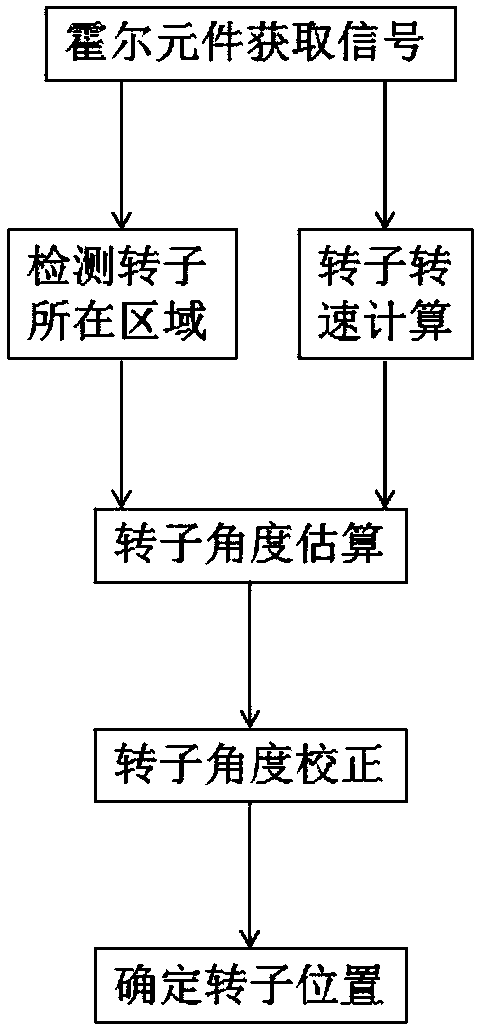
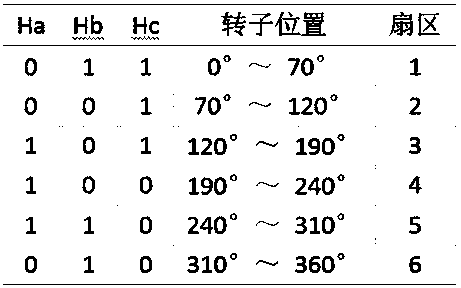
[0020] figure 1 It is a process flowchart of a method for detecting the rotor position of a permanent magnet synchronous motor for vehicles. After the Hall element obtains the signal, on the one hand, the corresponding relationship between the Hall signal and the rotor angle is used to determine which area the rotor is located in, and on the other hand, the rotor speed is calculated by the T method; it can be estimated according to the obtained rotor area and rotor speed Rotor angle; then correct the rotor angle by using the slow angle correction method, so that the position of the rotor can be determined.

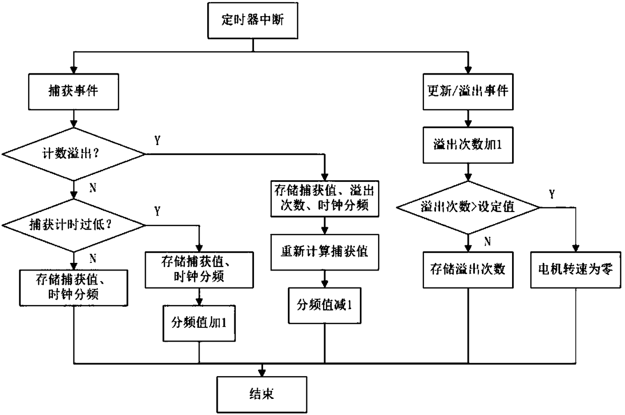
[0021] image 3 It is a flow chart of the process of setting the frequency division value of the input capture timer when calculating the rotational speed of a rotor position detection method of a permanent magnet synchronous motor for vehicles. Configu...


PUM


Abstract

The invention relates to a motor rotor position detection method, and specifically relates to position detection of a rotor of a permanent magnet synchronous motor. The method comprises the steps of installing three Hall elements at positions spacing from each other by 120-degree electrical angle of a stator side of the permanent magnet synchronous motor so as to acquire Hall signals, after Hall detection signals are obtained, on the one hand, determining which area the rotor is in according to a correspondence relationship of the Hall signal and the rotor angle, on the other hand, calculatinga rotor rotating speed through a T method; estimating the rotor angle according to the obtained area in which the rotor is and the rotor rotating speed; and correcting the rotor angle by using an angle slow correction method so as to determine the position of the rotor. In the method, the Hall elements are used to detect the position of the rotor, so that the method has the advantages of being low-cost, easy and convenient; a clock division value of a timer is corrected in real time, so that the optimal resolution is guaranteed; and the rotor angle is corrected by using the angle slow correction method, so that current fluctuation is reduced effectively, and the motor runs stably.

Description

technical field [0001] The invention relates to a motor rotor position detection method, in particular to a permanent magnet synchronous motor rotor position detection method. Background technique [0002] With the increasingly prominent energy shortage and the worsening of environmental pollution, electric vehicles, as a new energy vehicle driven by electric energy, have attracted more and more attention. Due to the advantages of small size, high efficiency, large overload capacity and fast response speed, the permanent magnet synchronous motor has occupied an important position in the servo field, and is an ideal choice for the electric drive system of electric vehicles. [0003] The control accuracy of permanent magnet synchronous motor depends largely on the accuracy of rotor position detection. The traditional method of obtaining the rotor position is realized by high-resolution position sensors such as resolvers and photoelectric encoders, which can accurately obtain ...

Claims


Application Information

Patent Timeline
Patent Type & Authority Applications(China)
IPC IPC(8): H02P6/17H02P23/14H02P25/022
CPCH02P6/17H02P23/14H02P25/024H02P2207/05
Inventor 宋宏帅王佐勋
Owner QILU UNIV OF TECH
Why Eureka
Try Eureka