Automatic rubber tapping robot

A robot and rubber tapping technology, applied in the field of robots, can solve the problems of complex structure of automatic rubber tapping machine, complex cutter head structure, short motor life, etc., and achieve the effect of easy mechanical and electrical protection, high cutting speed and low cost

Active Publication Date: 2018-08-17
CHONGQING UNIV
View PDF7 Cites 14 Cited by
  • Summary
  • Abstract
  • Description
  • Claims
  • Application Information

AI Technical Summary

Problems solved by technology

[0005] In view of this, the present invention provides an automatic rubber tapping robot to solve the problems of complex structure, low t

Method used


Image

  • Automatic rubber tapping robot
  • Automatic rubber tapping robot
  • Automatic rubber tapping robot

Examples


Embodiment Construction

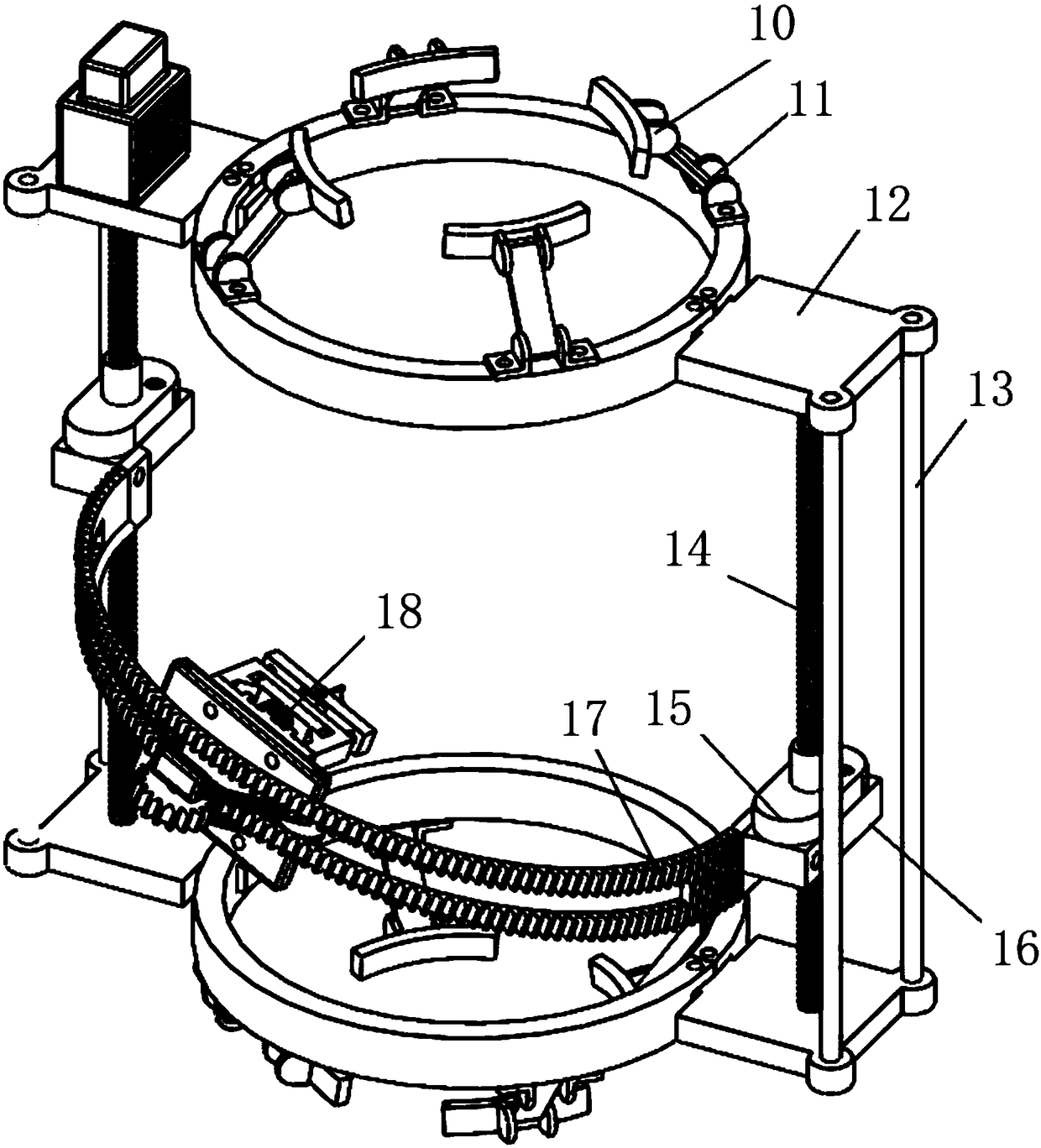
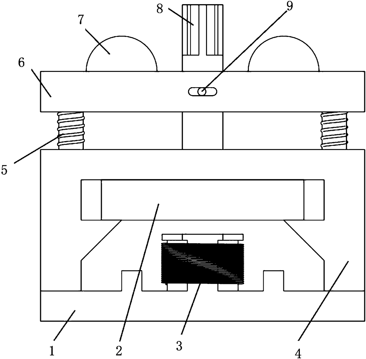
[0020] figure 1 It is an overall assembly drawing of the present invention; figure 2 It is a structural schematic diagram of the magnetic levitation cutter head 18 of the present invention; as shown in the figure: the automatic rubber tapping robot of this embodiment includes a magnetic levitation cutter head 18 and is used to attach the magnetic levitation cutter head 18 to the trunk and guide the magnetic levitation cutter head 18 A cutter head installation mechanism that moves along the trunk surface; the magnetic levitation cutter head 18 includes a base 1, a knife rest 6 elastically connected to the base 1, and a cutting knife 8 that is reciprocally slidingly fitted on the knife rest 6 with a single degree of freedom, like figure 2 As shown, the knife holder 6 is provided with a waist-shaped hole, and a cylindrical pin 9 slidingly fitted with the waist-shaped hole is fixed on the knife handle of the cutting knife 8, so that the cutting knife 8 can slide back and forth ...


PUM


Abstract

The invention discloses an automatic rubber tapping robot. The automatic rubber tapping robot comprises a magnetic suspension knife head and a knife head installation mechanism, wherein the knife headinstallation mechanism is used for making the magnetic suspension knife head attached to a tree trunk and guiding movement of the magnetic suspension knife head along the surface of the tree trunk. The magnetic suspension knife head comprises a base, a knife rest and a cutting knife, wherein the knife rest is elastically connected to the base, and the cutting knife reciprocates in a form of single degree of freedom and is slidably matched with the knife rest; the base is provided with a permanent magnet and an electromagnet opposite to the permanent magnet; the electromagnet drives the cutting knife connected with the permanent magnet to vibrate by continually changing polarity, so that cutting motion is completed. By means of the robot, the problems can be solved that in an existing automatic rubber tapping machine, the structure of a knife head is complicated, the rubber tapping efficiency is low, the service life of a motor is short, and the existing automatic rubber tapping machine is complicated in structure, difficult to control and high in cost.

Description

technical field [0001] The invention relates to the field of robots, in particular to an automatic tapping robot. Background technique [0002] Existing rubber tapping robot cutter head is mainly the cutter head driven by DC motor, and its main feature is that it is easy to control and can complete the rubber tapping action. The traditional motor is composed of a stator and a mover. The stator and the mover are connected by mechanical bearings or have mechanical contact, so there is mechanical friction during the movement of the mover. Mechanical friction not only increases the friction resistance of the mover, wears out the moving parts, produces mechanical vibration and noise, but also causes heating of the parts and deterioration of the performance of the lubricant. In severe cases, the air gap of the motor will be uneven, the winding will heat up, and the temperature rise will increase. Large, thereby reducing the efficiency of the motor, and ultimately shortening the s...

Claims


Application Information

Patent Timeline
IPC IPC(8): A01G23/10A01G23/12
CPCA01G23/10A01G23/12
Inventor 柏龙李鑫陈晓红杨建兴王卓
Owner CHONGQING UNIV
Why Eureka
Try Eureka