
Electric automatization dedusting equipment with excellent purifying effect

A technology of electrical automation and dust removal equipment, applied in the direction of electrode cleaning, electrostatic separation, electrode structure, etc., can solve the problems of high labor intensity, external environmental pollution, and high cost, and achieve the goal of improving dust removal efficiency, protecting the external environment, and reasonable design Effect

Active Publication Date: 2018-08-17
JIANGXI PACIFIC ENERGY SAVING & ENVIRONMENTAL PROTECTION TECH
View PDF8 Cites 3 Cited by
  • Summary
  • Abstract
  • Description
  • Claims
  • Application Information

AI Technical Summary

Problems solved by technology

The clean room requires that no matter how the external air conditions change, the room can maintain the cleanliness, temperature, humidity and pressure of the original set requirements, so stability is particularly important; in industrial production, boilers are used. A large amount of flue gas will be generated during the working process of the boiler. If it is directly discharged, it will cause serious pollution to the external environment and endanger the life safety of factory workers; The cost is expensive, and there are disadvantages of low efficiency and high energy consumption. It cannot reflect the theme of energy conservation and environmental protection. It will also cause serious pollution to the external environment and bring serious air quality and safety issues.

Method used


Image

  • Electric automatization dedusting equipment with excellent purifying effect
  • Electric automatization dedusting equipment with excellent purifying effect
  • Electric automatization dedusting equipment with excellent purifying effect

Examples


Embodiment Construction

[0022] The following will clearly and completely describe the technical solutions in the embodiments of the present invention with reference to the accompanying drawings in the embodiments of the present invention. Obviously, the described embodiments are only some, not all, embodiments of the present invention. Based on the embodiments of the present invention, all other embodiments obtained by persons of ordinary skill in the art without making creative efforts belong to the protection scope of the present invention.

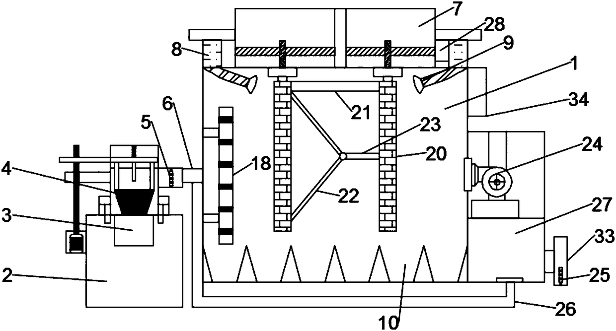
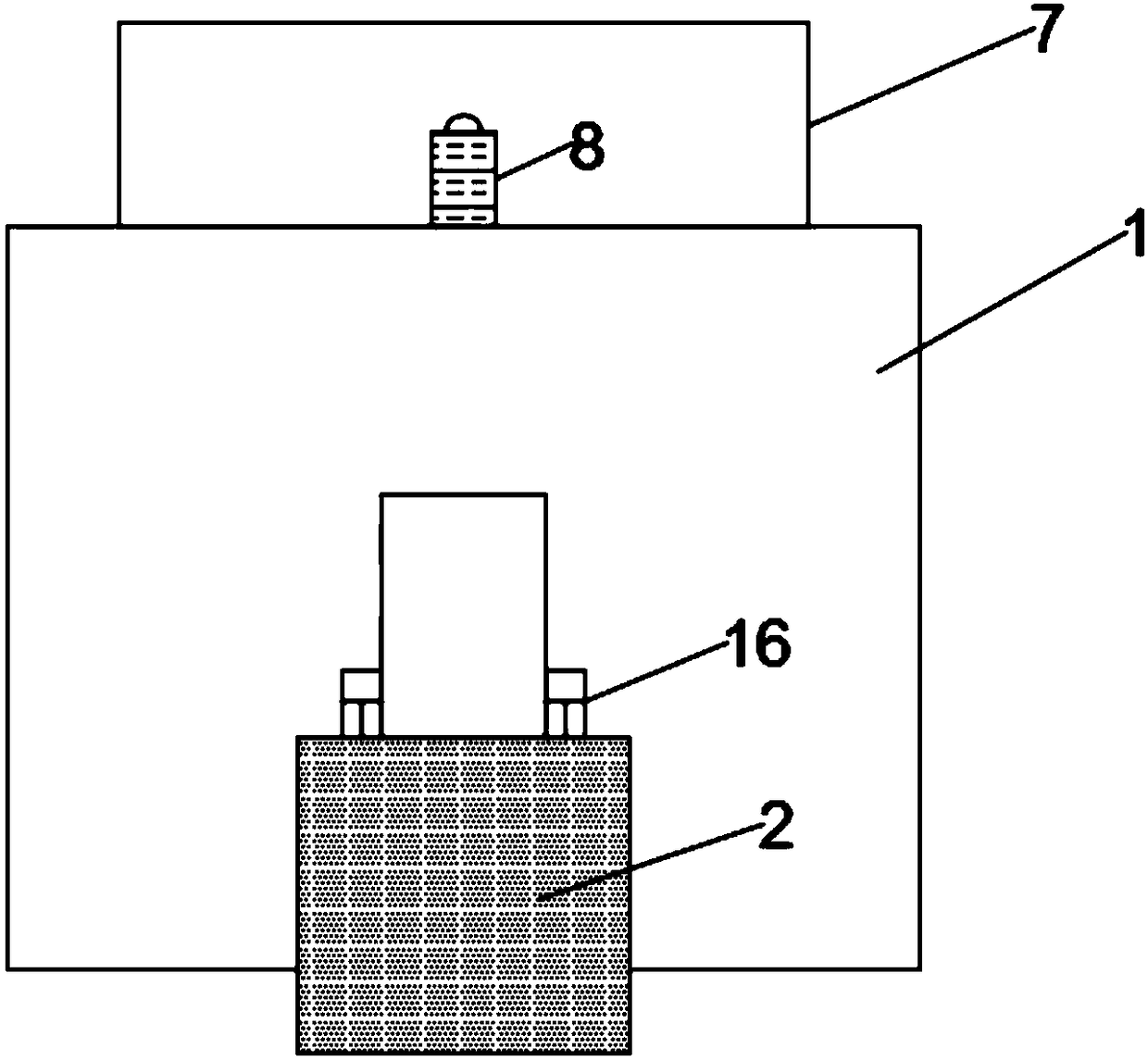
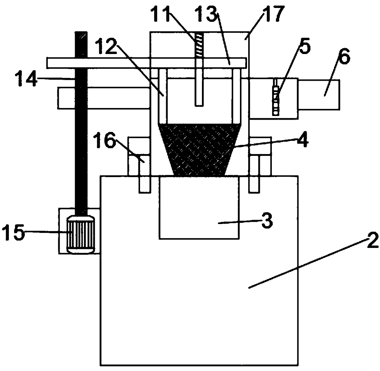
[0023] see Figure 1~5, in an embodiment of the present invention, an electrical automatic dust removal device with good purification effect includes a dust removal chamber 1, a smoke discharge chamber 2, a smoke discharge port 3, a piston valve 4 and a first smoke sensor 5, the dust removal chamber 1. A smoke discharge chamber 2 is provided on the left side. A smoke discharge port 3 is provided at the upper middle of the inner cavity of the smoke discharge ch...


PUM


Abstract

The invention discloses electric automatization dedusting equipment with an excellent purifying effect. The electric automatization dedusting equipment comprises a dedusting cavity, a flue gas emission cavity, a flue gas discharging hole and a first smoke sensor, wherein the flue gas emission cavity is formed in the left side of the dedusting cavity; the flue gas discharging hole is formed in themiddle of the upper part of the internal cavity of the flue gas emission cavity; a piston valve is arranged at the upper part of the flue gas discharging hole; first connecting rods are welded at thetwo ends of the upper surface of the piston valve; the upper ends of the first connecting rods extend into a movable cavity; a limiting rod is arranged in the middle of the interior of the movable cavity; a first connecting pipe is arranged on the right side of the limiting rod; and the first smoke sensor is arranged in the internal cavity at the left end of the first connecting pipe. The electricautomatization dedusting equipment is reasonable in design and convenient to operate, can fully adsorb dust in exhaust gas of a boiler rapidly, has the characteristics of high efficiency and energy conservation, ensures that exhaust gas of the boiler is clean and pollution-free when discharged, protects the external environment and prevents a worker from inhalation of the exhaust gas to avoid harm to life safety and health.

Description

technical field [0001] The invention relates to the technical field of electric dust removal, in particular to an electric automatic dust removal device with good purification effect. Background technique [0002] Electric dust removal device refers to the removal of particulates, harmful air, bacteria and other pollutants in the air within a certain space, and the indoor temperature, cleanliness, indoor pressure, air velocity and air distribution, noise vibration and lighting, static electricity, etc. Control within a certain range of needs, and give a specially designed room. The clean room requires that no matter how the external air conditions change, the room can maintain the cleanliness, temperature, humidity and pressure of the original set requirements, so stability is particularly important; in industrial production, boilers are used. A large amount of flue gas will be generated during the working process of the boiler. If it is directly discharged, it will cause s...

Claims


Application Information

Patent Timeline
IPC IPC(8): B03C3/04B03C3/36B03C3/47B03C3/76B03C3/34
CPCB03C3/04B03C3/34B03C3/36B03C3/363B03C3/368B03C3/47B03C3/76
Inventor 陈阳
Owner JIANGXI PACIFIC ENERGY SAVING & ENVIRONMENTAL PROTECTION TECH
Learn More