Centrifugal type sludge dehydrating device

A sludge dehydration and centrifugal technology, applied in water/sludge/sewage treatment, sludge treatment, water/sewage treatment, etc., can solve the problems of unfavorable environmental protection, bulky equipment, high cost of use, etc., to achieve environmental protection, Ease of use and miniaturization

Inactive Publication Date: 2018-08-17
CHONGQING JIAOTONG UNIVERSITY
View PDF4 Cites 5 Cited by
  • Summary
  • Abstract
  • Description
  • Claims
  • Application Information

AI Technical Summary

Problems solved by technology

[0002] With the intensification of human production activities, a large amount of sewage will be produced in the production activities, and flocculation and sedimentation are required to form sludge in the process of sewage treatment. Since the sludge contains more than 95% of water, in order to protect the environment, it is necessary to Dehydration of sludge, the existing sludge dewatering equipment has the following defects: Existing sludge dewatering equipment in press dehydration, centrifugal dehydration and other methods, among them, although press dehydration can be more fully dehydrated, but the structure is complex, the equipment It is bulky and expensive to use, which is not conducive to miniaturized sludge treatment. Although the existing centrifugal dewatering is beneficial to miniaturized sludge dewatering treatment, the sludge dewatering equipment with the existing structure cannot fully dehydrate, and often The water content of the treated sludge is still higher than the specified standard. When the sludge is directly landfilled, composted, etc., it will have a great impact on the environment and is not conducive to environmental protection

Method used


Image

  • Centrifugal type sludge dehydrating device
  • Centrifugal type sludge dehydrating device
  • Centrifugal type sludge dehydrating device

Examples


Embodiment Construction

[0031] Below in conjunction with accompanying drawing, the present invention is described in further detail, as shown in the figure:

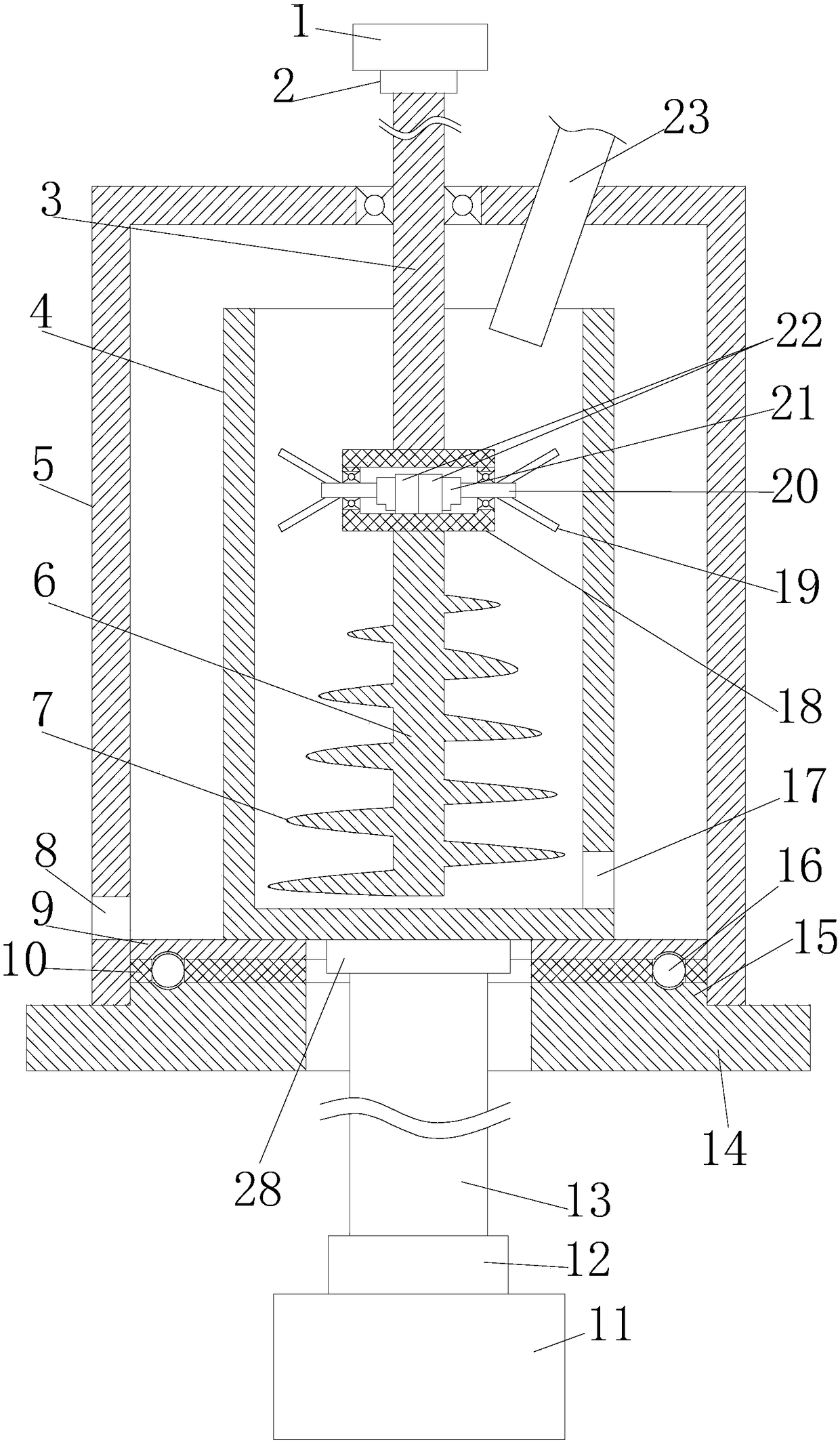
[0032] The purpose of the present invention is to provide a centrifugal sludge dewatering device, including a housing 5, a base 14, a centrifugal cylinder 4, a stirring mechanism, a first drive motor 1 and a second drive motor 11;

[0033] The shell 5 is a cylindrical structure and the shell 5 is turned upside down on the base 14 with the bottom facing upwards. The centrifugal cylinder 4 is coaxially arranged in the shell and the centrifugal cylinder 14 is fixedly arranged on the base 14 in a rotatable manner. , the second drive motor 11 drives the centrifugal cylinder 14 to rotate;

[0034] The stirring mechanism includes an upper drive shaft 3, an installation box 18, two third drive motors 22, two horizontal stirring shafts 20 and a vertical stirring shaft 6;

[0035] The upper end of the upper drive shaft 3 protrudes from the bottom of the...


PUM


Abstract

The invention aims to provide a centrifugal type sludge dehydrating device. The centrifugal type sludge dehydrating device comprises a housing, a base, a centrifugal barrel, a stirring mechanism, a first drive motor and a second drive motor, wherein the housing is of a tubular structure; the housing is reversely buckled on the base in a mode of enabling the bottom to face upwards; the centrifugalbarrel is coaxially arranged in the housing, and the centrifugal barrel can be fixedly arranged on the base in a rotatable mode; the stirring mechanism comprises an upper drive shaft, a mounting box,two third drive motors, two transverse stirring shafts and a longitudinal stirring shaft. The centrifugal type sludge dehydrating device can be used for sufficiently dehydrating sludge, so that the dehydrated sludge can reach specified water content standards, and therefore, follow-up treatment application is facilitated, environmental pollution is facilitated, miniaturization is facilitated and use is convenient.

Description

technical field [0001] The invention relates to sewage treatment equipment, in particular to a centrifugal sludge dewatering device. Background technique [0002] With the intensification of human production activities, a large amount of sewage will be produced in the production activities, and flocculation and sedimentation are required to form sludge in the process of sewage treatment. Since the sludge contains more than 95% of water, in order to protect the environment, it is necessary to Dehydration of sludge, the existing sludge dewatering equipment has the following defects: Existing sludge dewatering equipment in press dehydration, centrifugal dehydration and other methods, among them, although press dehydration can be more fully dehydrated, but the structure is complex, the equipment It is bulky and expensive to use, which is not conducive to miniaturized sludge treatment. Although the existing centrifugal dewatering is beneficial to miniaturized sludge dewatering tr...

Claims


Application Information

Patent Timeline
Patent Type & Authority Applications(China)
IPC IPC(8): C02F11/12
CPCC02F11/127C02F2201/002
Inventor 张沁王伟
Owner CHONGQING JIAOTONG UNIVERSITY
Why Eureka
Try Eureka