Water floating wind driven generator built on bamboo-wound composite pressure buoyancy tank

A wind power generator and pressure technology, which is applied in the direction of wind power storage, wind power generation, wind power motors, etc., can solve the problems that are not used to remove lake water pollutants, and achieve the effects of expanding employment, protecting the ecological environment, and increasing income

Inactive Publication Date: 2018-08-17
WUXI TONGCHUN NEW ENERGY TECH
View PDF4 Cites 0 Cited by
  • Summary
  • Abstract
  • Description
  • Claims
  • Application Information

AI Technical Summary

Problems solved by technology

The abundant wind resources on the lake are currently not being used to remove pollutants from the lake water

Method used


Image

  • Water floating wind driven generator built on bamboo-wound composite pressure buoyancy tank

Examples


Embodiment 1

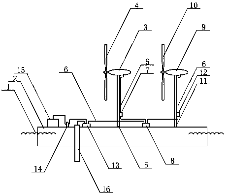
[0023] The wind power pillar armor is installed on the middle part of the upper surface of the bamboo winding composite pressure buoyancy tank, the horizontal axis wind power generator armor is installed on the top surface of the wind power pillar armor, the blade armor is installed at the front end of the horizontal axis wind power generator armor, and the wind power pillar armor is installed on the front end of the horizontal axis wind power generator armor. Wind power controller A is installed on the side of A, wind power prop B is installed on the rear portion of the upper surface of bamboo winding composite pressure buoyancy tank, horizontal axis wind power generator B is installed on the top surface of wind power prop B, and horizontal axis wind power generator B is installed on the top surface of wind power prop B. Blade B is installed on the front end of machine B, and wind power controller B is installed on the side of wind power pillar B. The wind blows blade A to rota...

Embodiment 2

[0025] The wind power pillar armor is installed on the middle part of the upper surface of the bamboo winding composite pressure buoyancy tank, the vertical axis wind power generator armor is installed on the top surface of the wind power pillar armor, and the blade armor is installed at the front end of the vertical axis wind power generator armor. Wind power controller A is installed on the side of A, wind power prop B is installed on the rear of the upper surface of the bamboo winding composite pressure buoyancy tank, vertical axis wind power generator B is installed on the top surface of wind power prop B, and vertical axis wind power generator B is installed on the top surface of wind power prop B. Blade B is installed on the front end of B, and wind power controller B is installed on the side of wind power pillar B. The wind blows blade A to rotate and drives the current generated by vertical axis wind power generator A to enter the smart confluence through conductive wire...


PUM


Abstract

The invention relates to a water floating wind driven generator built on a bamboo-wound composite pressure buoyancy tank, and belongs to the technical field of environmental protection. A wind power support column A and a wind power support column B are respectively mounted at the middle part and the back part of the upper surface of the bamboo-wound composite pressure buoyancy tank; a wind drivengenerator A and a wind power controller A provided with blades A at the front ends are mounted on the wind power support column A; a wind driven generator B and a wind power controller B provided with blades B at the front ends are mounted on the wind power support column B; wind power blows the blades A to drive current output by the wind driven generator A and to adjust the current through thewind power controller A; the wind power blows the blades B to drive current output by the wind driven generator B and to adjust the current through the wind power controller B; the two parts of current are input into an intelligent current gatherer through leads; the gathered current is supplied to an electric water quality purifier through a mixing wind power micro inverter; and through operationof the electric water quality purifier, sucked lake water is changed to purified water through a filter screen, and the purified water is drained into the water to improve the water quality.

Description

technical field [0001] The invention relates to a water floating wind power station built on a bamboo winding composite pressure buoyant tank, and belongs to the field of new environmental protection technologies. Background technique [0002] In order to cope with global climate change and reduce carbon emissions, China is vigorously developing clean energy. Wind energy is one of the important clean energy sources. In the process of wind power generation, no pollutants are emitted into the air. The average concentration of carbon dioxide in the atmosphere in April 2018 was higher than 410ppm. The development of wind power can reduce carbon dioxide emissions and mitigate climate change. The current offshore wind power is all column-type, and floating wind power stations on lakes and oceans are currently blank in China. [0003] Due to the pollution of water bodies caused by industrial wastewater and domestic sewage, and farmland drainage flowing into lakes, plastic partic...

Claims


Application Information

Patent Timeline
IPC IPC(8): F03D9/11F03D9/20F03D13/25B63B35/00
CPCB63B35/00F05B2240/93F03D9/11F03D9/20F03D13/25Y02E10/72Y02E10/727Y02E70/30
Inventor 林华
Owner WUXI TONGCHUN NEW ENERGY TECH
Why Eureka
Try Eureka