Micro-nano optical fiber EFPI sensor F-P cavity manufacturing device and method

A micro-nano optical fiber and sensor technology, applied in the direction of converting sensor output, using optical devices to transmit sensing components, measuring devices, etc., can solve the problems of increasing thermal expansion stress damage, affecting structural continuity, and not being able to withstand high temperatures. point, real-time monitoring, simple and convenient operation

CN108413995AActive Publication Date: 2018-08-17NORTH CHINA ELECTRIC POWER UNIV (BAODING)
7 Cites 3 Cited by

Patent Information

Authority / Receiving Office
CN · China
Current Assignee / Owner
Publication Date
2018-08-17

Smart Images

  • Figure 1
    Figure 1
  • Figure 2
    Figure 2
  • Figure 3
    Figure 3
Patent Text Reader

Abstract

The invention discloses a micro-nano optical fiber EFPI sensor F-P cavity manufacturing device and method belonging to the technical field of optical fiber sensing. The device is formed by a beam expanding, collimating and focusing optical path and a fabrication platform. The optical path comprises a laser, a beam expanding and collimating mirror, a fine tuning mechanism, a mirror and a focusing lens and is used for expanding, collimating and focusing a divergent laser beam into a micron-level parallel laser beam. The fabrication platform comprises horizontal and vertical rotation platforms and a linear sliding table and is used for realizing the integrated making of diaphragm cutting, diaphragm and capillary welding and fiber and capillary welding. According to the method, a shaped laserbeam is uniformly radiated to the surface of a welded surface of the fabrication platform, and the integrated construction of the fabrication platform is used to carry out precise welding sealing on an optical fiber EFPI sensor by using the integrated structure of the manufacturing platform. The manufacturing process of the invention is integrated and continuous, the operation is simple and convenient, welding spot are effectively ensured to be uniform, the functions of real-time monitoring and automatic feedback can be realized by using the micrometer-level cavity length adjustment technology, and the micro-nano optical fiber EFPI sensor F-P cavity manufacturing device and method have important application values.
Need to check novelty before this filing date? Find Prior Art

Description

technical field

[0001] The invention belongs to the technical field of optical fiber sensing, and in particular relates to a device and method for fabricating an F-P cavity of a micronano optical fiber EFPI sensor. Background technique

[0002] With the continuous development of fiber optic communication technology in the field of national defense science and industry, fiber optic sensors have also been widely used. Compared with other sensors, fiber optic sensors have the characteristics of zero electromagnetic interference, and are especially suitable for online monitoring and fault diagnosis of power systems. Optical fiber sensing technology uses quartz glass optical fiber as the light transmission medium, uses the ability of optical signals to sense and detect external change signals, and uses photoelectric conversion technology to process strained optical signals and demodulate external parameter change signals. Optical fiber sensing sensors have been widely used and im...

Examples

Embodiment Construction

[0026] The present invention will be described in detail below in conjunction with the accompanying drawings and embodiments.

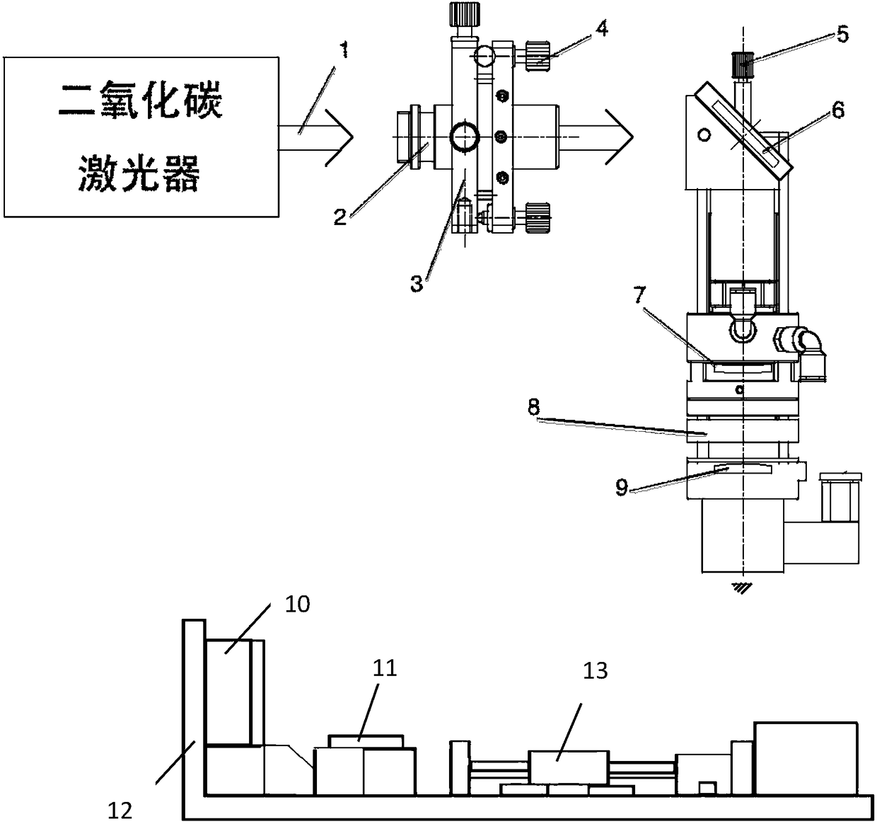
[0027] attached figure 1 Schematic diagram of the device structure for a micro-nano optical fiber EFPI sensor F-P cavity, such as figure 1 As shown, the device includes: a laser beam expansion collimation focusing optical path and a sensor manufacturing platform,

[0028] The laser beam expansion, collimation and focusing optical path is composed of three parts. The first part is a carbon dioxide laser 1, which is used as a welding laser heat source; The beam expander and collimator mirror 2 is located at the front end of the beam expander collimator barrel 3, and the position and angle of the laser beam incident on the reflector 6 are adjusted through the four jackscrews 4 on the beam expander collimator barrel 3 The third part includes a fine-tuning mechanism 5, a mirror 6, a focusing lens 7, a mirror barrel 8, and a focusing lens 9 connected in s...