Unmanned aerial vehicle tunnel inspection method based on BIM technology

A technology of unmanned aerial vehicles and tunnels, which is used in three-dimensional position/channel control, instruments, surveying and navigation, etc., and can solve the problems of low navigation accuracy.

Inactive Publication Date: 2018-08-17
SHANGHAI UNIV
View PDF7 Cites 20 Cited by
  • Summary
  • Abstract
  • Description
  • Claims
  • Application Information

AI Technical Summary

Problems solved by technology

[0003] From the patents searched at home and abroad, there is no patent on the application of drones to tunnel inspection lines. This is because there are many lines in the tunnel, and no matter how precisely the d

Method used


Image

  • Unmanned aerial vehicle tunnel inspection method based on BIM technology
  • Unmanned aerial vehicle tunnel inspection method based on BIM technology
  • Unmanned aerial vehicle tunnel inspection method based on BIM technology

Examples


Embodiment 1

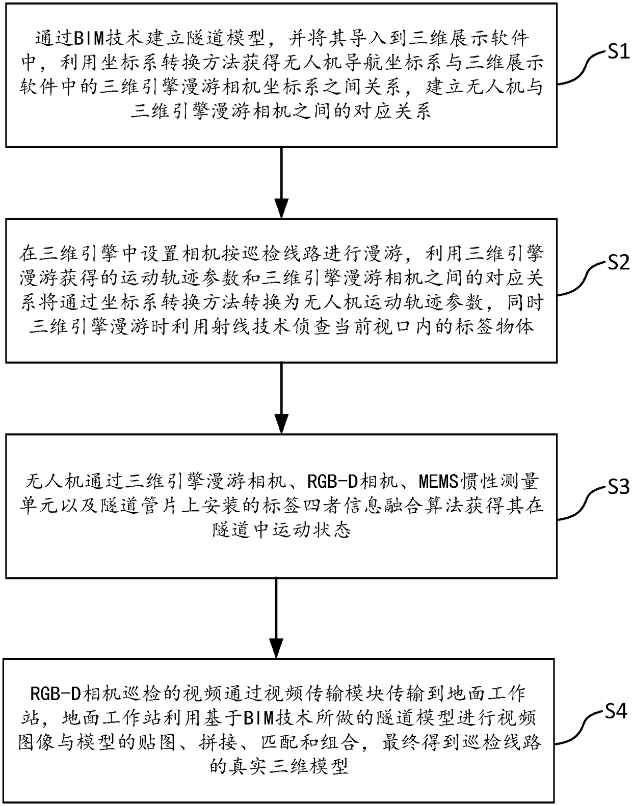
[0100] see figure 1 , the UAV tunnel inspection method based on BIM technology, the inspection method includes the following steps:

[0101] [Step S1] Establish the tunnel model through BIM technology, and import it into the 3D display software, use the coordinate system conversion method to obtain the relationship between the UAV navigation coordinate system and the 3D engine camera coordinate system, and establish the UAV and 3D engine Correspondence between cameras;

[0102] [Step S2] Set the camera in the 3D engine of the 3D display software on the ground workstation to roam according to the inspection route, and the corresponding relationship between the motion trajectory parameters obtained by using the 3D engine roaming and the 3D engine camera will be transformed into an unmanned model by the coordinate system conversion method. At the same time, the 3D engine uses ray technology to detect the tag object in the current viewport when roaming, so as to confirm with the ...

Embodiment 2

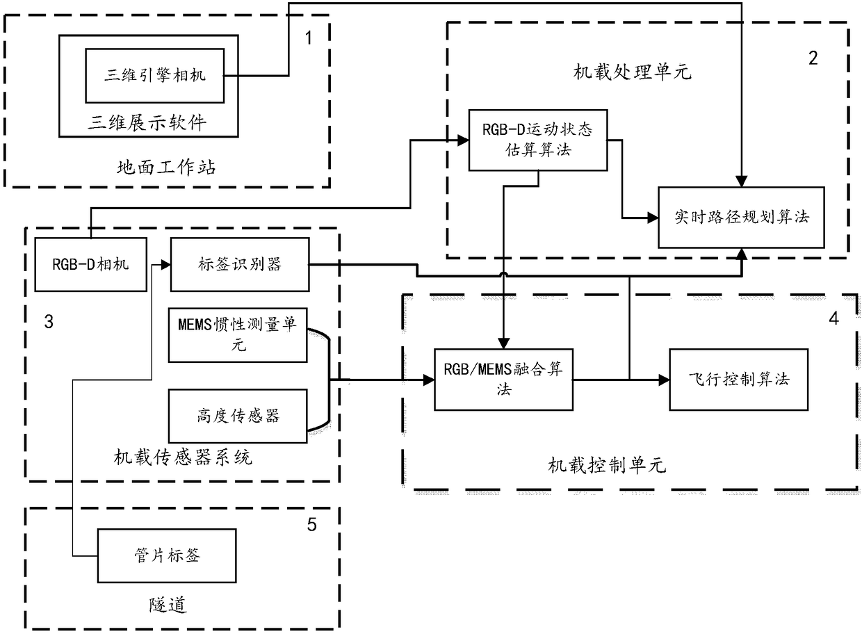
[0106] see figure 1 , figure 2 , the UAV tunnel inspection method based on BIM technology, which includes the following steps:

[0107] [Step 1] Establish the tunnel model through BIM technology, and import it into the 3D display software, use the coordinate system conversion method to obtain the relationship between the UAV navigation coordinate system and the 3D engine camera coordinate system, and establish the UAV and 3D engine Correspondence between cameras;

[0108] Among them, the coordinate system conversion method obtains the relationship between the UAV navigation coordinate system and the 3D engine camera coordinate system. The relationship is obtained first by obtaining the left, right, and upper distances of the UAV from the tunnel through the RGB-D camera, adjusting the UAV to the same position as the starting coordinates of the 3D engine roaming, so that the two coordinate systems coincide, and then using The quaternion performs the rotation transformation o...


PUM


Abstract

The invention discloses an unmanned aerial vehicle tunnel inspection method based on an BIM technology. The method comprises the following steps of through a BIM technology, establishing a tunnel model, guiding into a three-dimensional engine, using a coordinate system conversion method to acquire the relationship between an unmanned aerial vehicle navigation coordinate system and a three-dimensional engine camera coordinate system, and establishing a corresponding relation between a unmanned aerial vehicle and a three-dimensional engine camera; in the three-dimensional engine, arranging a camera to carry out roaming according to an inspection line, and through the coordinate system conversion method, converting into a unmanned aerial vehicle motion track parameter; acquiring a motion state in a tunnel through an information fusion algorithm by the unmanned aerial vehicle; and transmitting an RGB-D camera inspection video to a ground work station through a video transmission module, using a tunnel model made based on the BIM technology to carry out mapping, splicing, matching and combining of video images and models, and finally acquiring the real three-dimensional model of the inspection line. And then, the specific condition of the current line and whether there is a tunnel disease risk are clearly grasped. In the invention, the work efficiency of tunnel inspection can be accelerated.

Description

technical field [0001] The invention belongs to the technical field of tunnel inspection and relates to a tunnel inspection method, in particular to an unmanned aerial vehicle inspection method based on BIM technology. Background technique [0002] The methods commonly used in tunnel inspection at home and abroad mainly include manual inspection and semi-automatic instrument inspection. Among them, manual inspection can only take two or three hours for inspection due to the daily operation of the tunnel, which results in very short manual inspection lines. Semi-automatic instrument detection requires pre-embedded detection sensors during tunnel production, and can only be carried out by setting up special communication equipment during tunnel operation. Moreover, the survival rate of pre-embedded sensors is not very high, which has led to the current tunnel inspection. It is still carried out mainly by manual inspection. [0003] From the patents searched at home and abroa...

Claims


Application Information

Patent Timeline
IPC IPC(8): G05D1/10G01C21/16G01C11/02
CPCG01C11/02G01C21/165G05D1/101
Inventor 高新闻简明胡珉林欣欣周显威
Owner SHANGHAI UNIV
Why Eureka
Try Eureka