Blow molding machine head

A technology of blow molding head and head, which is applied in the field of blow molding on blow molding machines, can solve problems such as increasing production costs, reducing product quality, and thermal oxidation reactions, and achieves uniform distribution, reduced processing costs, and reduced material degradation. Effect

Inactive Publication Date: 2018-08-21
SHANDONG QINGTIAN PLASTIC IND
View PDF0 Cites 0 Cited by
  • Summary
  • Abstract
  • Description
  • Claims
  • Application Information

AI Technical Summary

Problems solved by technology

Usually, before the material enters the spiral flow channel, it needs to be distributed through a distributor. The existing distributor usually has a long flow channel, and the material is prone to thermal oxidation reaction in the equipment, resulting in paste, reducing product quality and increasing production costs.

Method used


Image

  • Blow molding machine head
  • Blow molding machine head
  • Blow molding machine head

Examples


Embodiment Construction

[0022] The present invention will be further described below in conjunction with accompanying drawing:

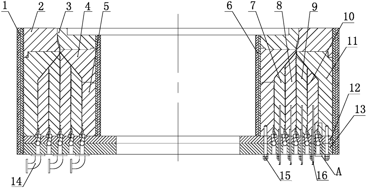
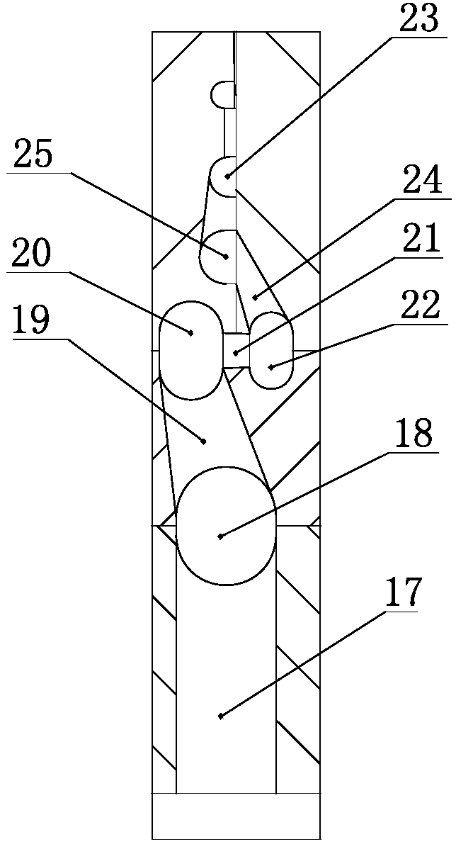
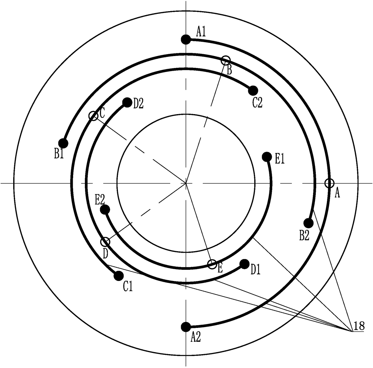
[0023] Such as Figure 1 to Figure 7 As shown, the blow molding machine head of the present invention includes an annular machine head body 11, and five layers of annular helicoids are arranged inside the machine head body 11, which are respectively inner helix I5, inner helix II7, middle helix 8, outer helix II9 and Outer helix I10, the upper part of the helix has a lower die 4, the upper part of the lower die 4 has an upper die 3, the outer side of the upper die 3 is an adjustment ring 2, and a spiral channel 23 is formed between two adjacent helicoids, and the bottom of the spiral channel 23 is set Splitter plate, the bottom of the splitter plate is evenly distributed with feeding ports along the circumferential direction of the spiral channel 23, and each feeding port is set corresponding to one of the spiral channels 23, and the inside of the splitter plate is vertical...


PUM

PropertyMeasurementUnit
thicknessaaaaaaaaaa

Abstract

The invention is mainly applied to the field of blow molding of blow molding machines, and particularly relates to a blow molding machine head which comprises a machine head. Annular spiral channels are distributed inside the machine head, distribution plates are arranged at the bottoms of the spiral channels, an inlet runner which is communicated with a corresponding feed inlet is vertically arranged inside each distribution plate, a one-to-two runner is communicated with the top of each inlet runner, two ends of each one-to-two runner are communicated with the bottoms of vertical communication holes, two-to-four runners are communicated with the tops of the vertical communication holes, each of two ends of each two-to-four runner is communicated with an end of a horizontal communicationhole, the other end of each horizontal communication hole is communicated with a four-to-eight runner, two ends of each four-to-eight runner are positioned on two sides of the corresponding horizontalcommunication holes, the tail end of each four-to-eight runner is upwardly connected with an eight-to-sixteen runner, the tail ends of the eight-to-sixteen runners are communicated with annular channels, and each spiral channel is communicated with the corresponding annular channel. The blow molding machine head has the advantages that the lengths of runners can be shortened to a great extent, material burning conditions can be reduced, and accordingly the product quality can be enhanced; intermediate cavities are reserved, and accordingly dies can be conveniently replaced at any time.

Description

technical field [0001] The invention relates to a blow molding machine head, which is mainly used in the field of blow molding on a blow molding machine. Background technique [0002] When the multi-layer co-extrusion blown film machine is working, the molten materials of each layer are distributed in the blown film head, and finally merged and extruded at the circular die to form a multi-layer co-extruded film bubble. When working, the molten material enters from each feed port, and then rotates and rises along each spiral flow channel. During the flow process of rotating and rising along each spiral groove flow channel, the molten material continues to flow from between every two layers of concentric sleeves. As the material rotates and rises, the proportion of the material moving axially along the spiral channel becomes smaller and smaller, while the proportion of material leaking upward along the annular gap becomes larger and larger, and finally all the molten material ...

Claims


Application Information

Patent Timeline
Patent Type & Authority Applications(China)
IPC IPC(8): B29C49/04B29C47/16B29C48/31
CPCB29C48/30B29C48/307B29C48/31B29C49/0015B29C49/04B29C49/0691
Inventor 马之清张熠吴建喜何敬国薛希忠
Owner SHANDONG QINGTIAN PLASTIC IND
Why Eureka
Try Eureka