Inner ring type seabed suction anchor for deep sea and installation method thereof

A suction anchor and suction technology, applied in construction, infrastructure engineering and other directions, can solve the problems of high construction cost, increased side friction resistance, loss of vertical bearing capacity and anti-pull bearing capacity, etc., to improve vertical bearing capacity and Pull-out resistance, enhanced pull-out bearing capacity, and the effect of reducing pore water pressure

Active Publication Date: 2018-08-21
ZHEJIANG UNIV
View PDF11 Cites 14 Cited by
  • Summary
  • Abstract
  • Description
  • Claims
  • Application Information

AI Technical Summary

Problems solved by technology

The suction anchor includes an anchor barrel and a reinforcing plate connected with a skirt, which solves the problems of high construction cost of the suction foundation, small horizontal bearing capacity, and erosion of the seabed soil around the upper part of the barrel, but the suction anchor cannot increase the lateral Frictional resistance, unable to improve the vertical bearing capacity and ultimate uplift bearing capacity of the suction anchor
[0008] (3) The Chinese patent application number 200910225767.3 introduces an expansion-tight deep-sea suction anchor and its installation method. The suction anchor can increase the vertical bearing capacity and pull-out resistance of the deep-sea anchor, but the suction anchor cannot greatly increase Side friction resistance, the installation method is complicated and cannot greatly improve the vertical bearing capacity and ultimate uplift bearing capacity of the suction anchor
The suction anchor includes an anchor bucket, an attached skirt, multiple tension chains and guide rings, and has a good vertical ultimate bearing capacity, but the suction anchor cannot greatly increase the side friction resistance, and its installation method is complicated and cannot be greatly improved. Suction anchor vertical bearing capacity and ultimate uplift bearing capacity
[0011] (6) The Chinese patent with the application number 201610523474.3 introduces a deep-sea bamboo-style suction anchor, which includes a bamboo-style anchor bucket, bearings and a rotatable nozzle, which can improve the vertical bearing capacity and limit resistance of the suction anchor. Pull-out bearing capacity, but only using the side contact with the soil, the ultimate pull-out bearing capacity cannot be greatly improved. At the same time, because the outside of the barrel is bamboo-shaped, there is greater resistance when the suction anchor sinks under the gravity and penetrates through the soil. , in the process of suction anchor penetration, the disturbance to the soil outside the barrel is relatively large, and the vertical bearing capacity and pull-out bearing capacity of the foundation are greatly lost in the early stage of foundation completion.
At the same time, the bamboo-shaped form outside the barrel also affects the recycling of the suction anchor
[0012] (7) The Chinese patent application number 201720217185.0 introduces a new type of submarine skirt suction anchor, which includes a concentric suction main barrel, a double skirt structure and an annular groove, which can lift the skirt suction anchor and the surrounding The contact area of ​​the soil increases the friction between the side of the foundation and the soil, but similarly, the annular groove set outside the suction anchor bucket has greater resistance when the suction anchor sinks and penetrates under gravity. During the penetration process of the suction anchor, the disturbance to the soil outside the barrel is relatively large, and the vertical bearing capacity and the uplift bearing capacity of the foundation are greatly lost in the early stage of foundation completion.
The ring groove on the outside of the barrel also affects the recovery of the suction anchor

Method used


Image

  • Inner ring type seabed suction anchor for deep sea and installation method thereof
  • Inner ring type seabed suction anchor for deep sea and installation method thereof
  • Inner ring type seabed suction anchor for deep sea and installation method thereof

Examples


Embodiment Construction

[0034] In order to make the technical solutions, goals and effects of the present invention clearer, the present invention will be further described below in conjunction with the accompanying drawings and embodiments.

[0035] The structures, proportions, sizes, etc. shown in the drawings attached to this specification are only used to match the content disclosed in the specification for the understanding and reading of those who are familiar with this technology, and are not used to limit the conditions for the implementation of the present invention , so it has no technical substantive meaning, and any modification of structure, change of proportional relationship or adjustment of size shall still fall within the scope of the disclosure of the present invention without affecting the functions and objectives of the present invention. The technical content must be within the scope covered. At the same time, terms such as "upper", "lower", "left", "right", "middle" and "one" qu...


PUM


Abstract

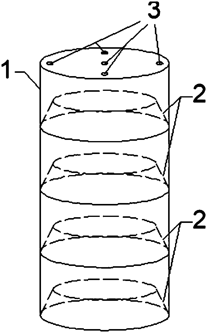
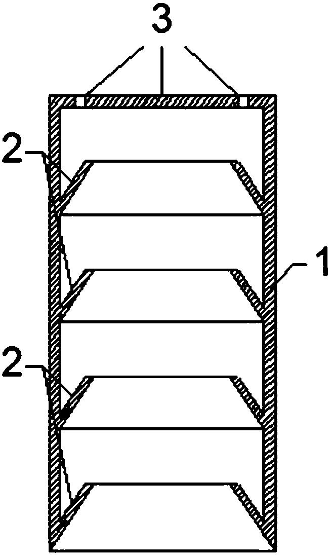
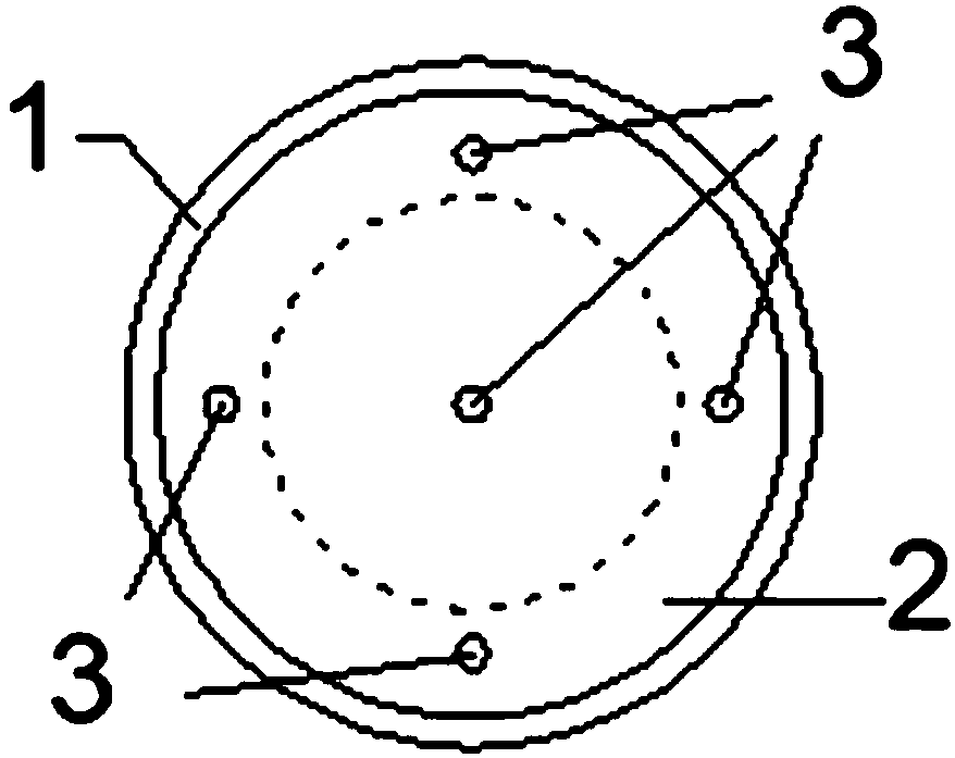
The invention discloses an inner ring type seabed suction anchor for deep sea and an installation method thereof. The suction anchor comprises a suction main barrel, the suction main barrel is of a barrel type structure of which the bottom is opened and the top end is closed, the inner wall of the suction main barrel is provided with a plurality of hollow annular bulges at equal intervals along anaxial direction, the inner wall of the suction main barrel and the side walls of the hollow annular bulges form a barb-shaped structure, and the center and the edges of the top of the suction main barrel are provided with drainage holes. The suction anchor can more smoothly sink and penetrate into the soil, can sink to the preset design depth, reduces the disturbance to the soil outside the barrel to the maximum extent under the effect of increasing side friction resistance, and reduces the erosion of sea waves on existing foundations; the vertical bearing capacity and the ultimate pull-out resistance bearing capacity of the suction anchor can be greatly improved under various working conditions; and under the condition of realizing the functions, the convenience of recycling the suctionanchor can also be ensured.

Description

technical field [0001] The invention belongs to the technical field of offshore wind power engineering and marine engineering in civil engineering, and relates to foundations of offshore wind turbines, mooring of offshore platforms, positioning of buoys, lighthouses, and structural foundations of jackets, in particular to a new type of seabed suction anchor and its installation method. Background technique [0002] With the accelerated development of offshore oil and gas resources exploitation and the rise of offshore wind power generation, the basic design of offshore drilling platforms and offshore wind farms has become an important topic in this field. As a new type of offshore structural facility, suction anchors have been widely used in ship mooring, buoy positioning, storage facilities, lighthouses, jackets, and offshore platforms. [0003] The suction anchor foundation is similar to the rigid short pile. The most widely used suction anchor in actual engineering is a ...

Claims


Application Information

Patent Timeline
Patent Type & Authority Applications(China)
IPC IPC(8): E02D27/52
CPCE02D27/525
Inventor 胡安峰南博文付鹏李唐
Owner ZHEJIANG UNIV
Why Eureka
Try Eureka