Photoelectric heating self-blasting drying device with heat storage function

A blast drying and photoelectric technology, applied in the direction of heating device, drying gas arrangement, static material dryer, etc., can solve the problems of unsatisfactory drying effect, poor integrity, low drying temperature, etc., and achieve increased retention and replacement Heat time, enhanced heat transfer effect, faster heating effect

Inactive Publication Date: 2018-08-21
GUIZHOU UNIV
View PDF7 Cites 2 Cited by
  • Summary
  • Abstract
  • Description
  • Claims
  • Application Information

AI Technical Summary

Problems solved by technology

[0002] Generally, the drying method of agricultural products is natural drying, the drying temperature is low, the drying time is long, and the drying conditions (such as sunlight intensity, customs, relative air humidity, etc.) Factors of pollution erosion, drying effect is not ideal
[0003] At present, there are mainly two types of solar dryers: one is a common greenhouse-type solar drying device, and the other is a collector-type solar drying device. The air collector and drying chamber of this drying device are separated. , so it can be better combined with the conventional energy air heating system to form a large-scale hybrid solar drying device with continuous operation, which uses solar energy to partially replace conventional energy to reduce fuel consumption and improve economic benefits, but its drying heat transfer process uses convection Heat exchange is the main method, and there is an additional heat exchange process between solar energy and materials, which is lower than the drying efficiency of ordinary greenhouse solar drying devices
The collector-greenhouse solar drying device that combines the advantages of the two dryers has a large system, poor integrity, and is expensive

Method used


Image

  • Photoelectric heating self-blasting drying device with heat storage function
  • Photoelectric heating self-blasting drying device with heat storage function
  • Photoelectric heating self-blasting drying device with heat storage function

Examples


Embodiment 1

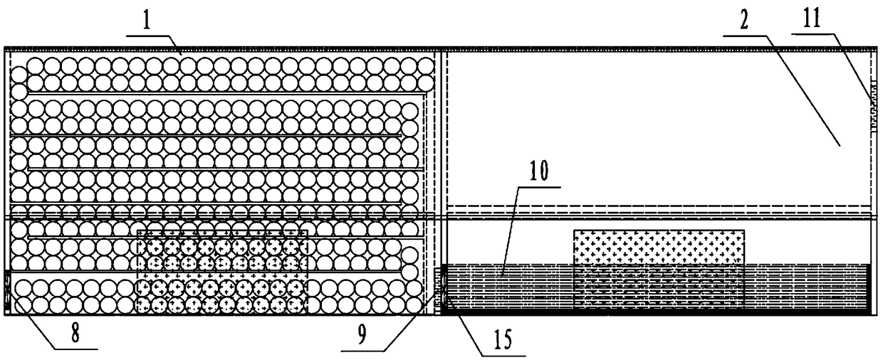
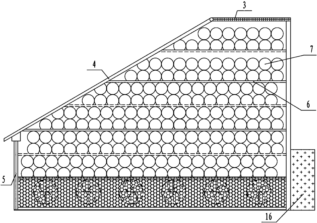
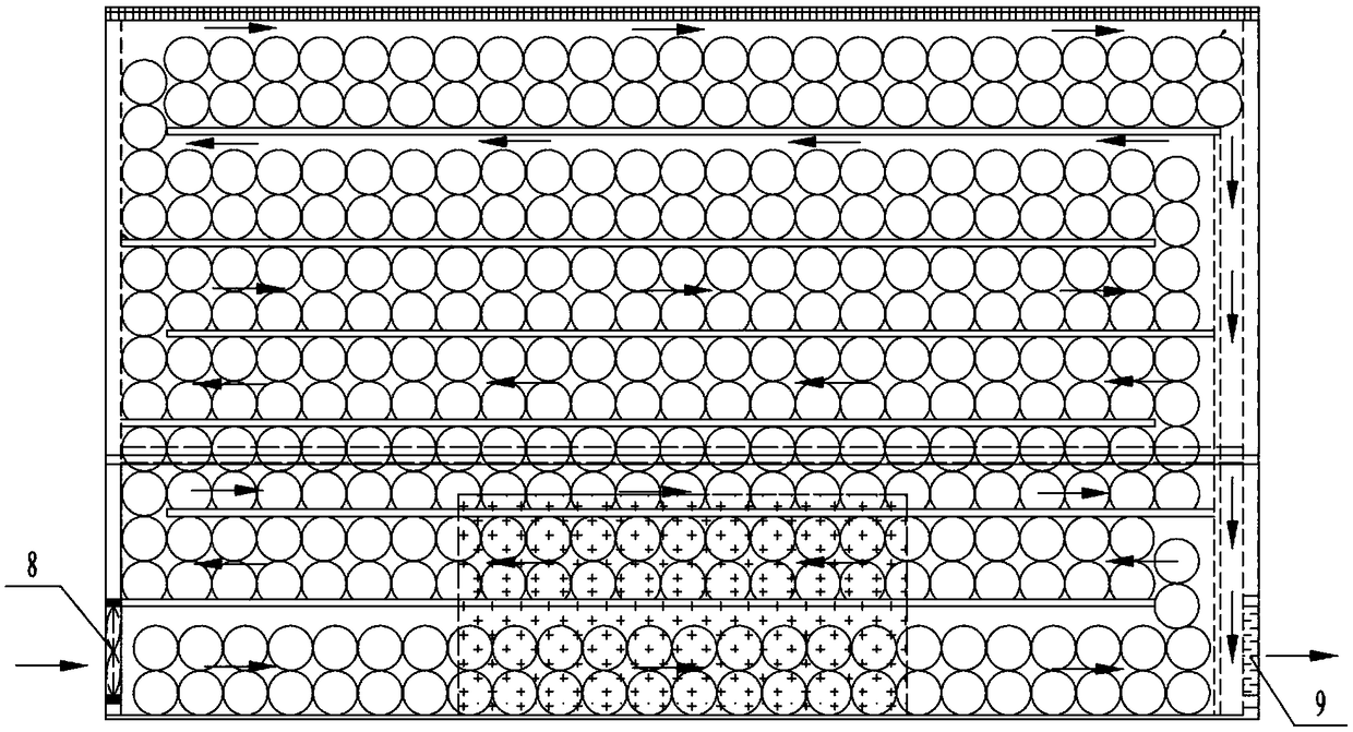
[0028] Embodiment 1: as Figure 1-Figure 8 As shown, a photoelectric thermal self-blowing drying device with heat storage function includes a heat storage device 1 and a drier 2, the heat storage device 1 is a box structure, and the top rear end is provided with a solar cell panel-3, and the solar cell The front end of the plate 3 is hinged with an inclined glass cover plate 4, and the other end of the glass cover plate 4 is fixedly connected with a vertical support plate 5. The support plate 5 is located at the front side of the heat storage device 1. A plurality of transparent partitions 6 are provided, and the front and rear sides of the transparent partitions 6 are fixed and sealed. The bottom air inlet of the shaped communication structure is provided with a fan unit 8, and the top air outlet is connected to the hot air outlet 9 at the bottom through the vertical channel on the right side of the heat storage device 1, and the hot air outlet 9 is connected to the air inlet...


PUM


Abstract

The invention discloses a photoelectric heating self-blasting drying device with a heat storage function. The device comprises a heat storage device and a drying device; the heat storage device is ofa box body structure, a first solar cell panel is arranged on the rear end of the top, a first glass cover plate which is inclined is hinged to the edge of the front end of the first solar cell panel,a first supporting plate which is vertical is fixedly connected to the first glass cover plate, the first supporting plate is located on the front side of the heat storage device, multiple transparent partition boards are arranged in the heat storage device, the front sides and the rear sides of the transparent partition boards are fixedly connected in a sealed manner, gaps on the left and rightside ends are arranged in a spaced manner, and a snake-shaped communication structure is formed; a heat storage material layer is arranged on each transparent partition board, a fan set is arranged onan air inlet in the bottom of the snake-shaped communication structure, an air outlet in the top is connected with a hot air outlet in the bottom, the hot air outlet is communicated with an air inletin the bottom of the drying device, a material paving net is arranged in the drying device, and an exhaust opening is formed in the upper end of the drying device. The heat exchange effect of a heatstorage material and air can be improved, it is ensured that the heating and temperature rise are rapier, and the utilization rate is greatly improved.

Description

technical field [0001] The invention belongs to the technical field of drying ovens, and in particular relates to a photoelectric thermal self-blowing drying device with heat storage function. Background technique [0002] Generally, the drying method of agricultural products is natural drying, the drying temperature is low, the drying time is long, and the drying conditions (such as sunlight intensity, customs, relative air humidity, etc.) Factors of pollution erosion, drying effect is not ideal. [0003] At present, there are mainly two types of solar dryers: one is a common greenhouse-type solar drying device, and the other is a collector-type solar drying device. The air collector and drying chamber of this drying device are separated. , so it can be better combined with the conventional energy air heating system to form a large-scale hybrid solar drying device with continuous operation, which uses solar energy to partially replace conventional energy to reduce fuel con...

Claims


Application Information

Patent Timeline
Patent Type & Authority Applications(China)
IPC IPC(8): F26B9/06F26B21/00F26B23/00F26B25/00
CPCF26B9/06F26B21/00F26B23/00F26B25/00
Inventor 申甲龚德鸿戴敏
Owner GUIZHOU UNIV
Why Eureka
Try Eureka