Method for detecting influences of gravity on optical axis direction of lens

A technology of optical axis pointing and detection method, which is applied in the field of optical remote sensors, can solve problems such as changes in optical axis pointing, and achieve the effects of small size, easy operation, and small environmental conditions

Active Publication Date: 2018-08-21
BEIJING RES INST OF SPATIAL MECHANICAL & ELECTRICAL TECH
View PDF8 Cites 10 Cited by
  • Summary
  • Abstract
  • Description
  • Claims
  • Application Information

AI Technical Summary

Problems solved by technology

[0008] The technical problem to be solved by the present invention is: to overcome the deficiencies of the prior art, the present invention provides a detection method for the influence of gravity on the optical axis of the lens, and solves the problem

Method used


Image

  • Method for detecting influences of gravity on optical axis direction of lens
  • Method for detecting influences of gravity on optical axis direction of lens
  • Method for detecting influences of gravity on optical axis direction of lens

Examples


Embodiment Construction

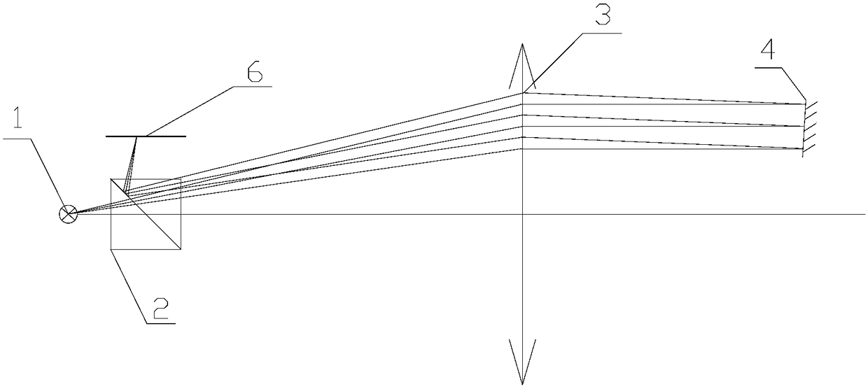
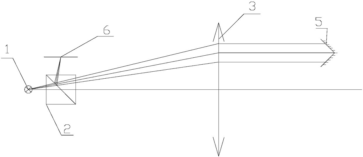
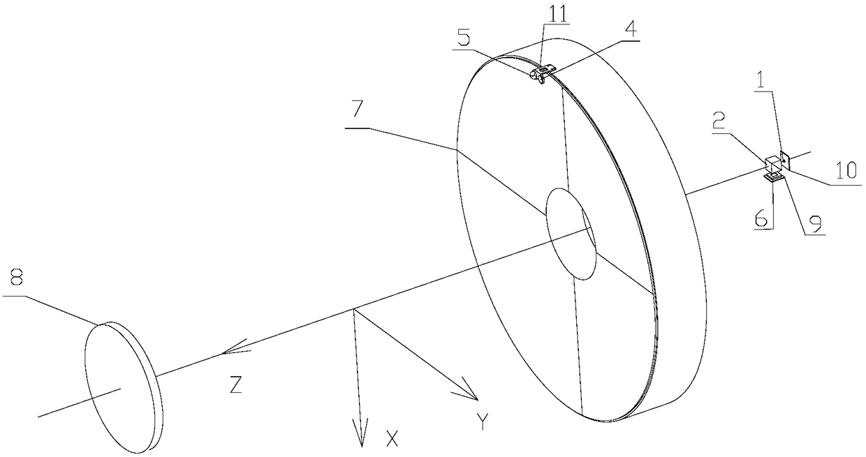
[0032] Such as figure 1 , figure 2 As shown, the detection method of the present invention adopts the principle of self-collimation, utilizes the large-diameter optical lens that has been assembled and adjusted, and installs a light source 1 on the focal plane position of the lens, and the light emitted by the light source 1 passes through a semi-reflective and semi-transparent prism 2 And optical lens 3 after exit. A plane mirror 4 and a corner cube prism 5 are installed on the edge of the front end of the optical lens 3 caliber. Light rays in different sub-apertures emitted from the optical lens 3 enter the optical lens 3 again after being reflected by the plane reflector 4 and the corner cube prism 5 . After being reflected by the half-reflective prism 2, they are respectively imaged on the receiving device 6. Since the incident angles of the light reflected by the plane reflector 4 and the light reflected by the corner cube prism are different, two spot images will be ...


PUM


Abstract

The invention provides a method for detecting influences of the gravity on the optical axis direction of a lens. According to the invention, a self-collimation technique of an optical system of the lens is utilized, a light source and a receiving device are installed on a focal plane of the optical lens, and a small-plane reflecting mirror and a pyramid prism are additionally arranged at a light inlet of the lens. The central positions of a light spot formed by the reflected light of the small-plane reflecting mirror on the receiving device and a reference light spot formed by reflected lightof the pyramid prism by using an image centroid algorithm, and the change of the optical axis direction can be obtained with high precision according to the change in central position of the light spot before and after the optical axis direction changes.

Description

technical field [0001] The invention belongs to the technical field of optical remote sensors and relates to a method for detecting changes in the direction of the optical axis of an optical lens. Background technique [0002] The optical axis pointing detection of the optical lens is an essential and important link in the process of adjusting the optical lens of the space optical remote sensor. In the large aperture and long focal length optical lens, the size of the mirror is large, the quality of the surface shape is high, and the relative position between the mirrors is difficult to fix. The optical axis of the optical lens will change due to the influence of the external environment during the development process of the assembly test, such as changes in the temperature environment. In order to detect changes in the optical axis of the optical system under different environmental conditions in real time, it is necessary to detect changes in the direction of the optical ...

Claims


Application Information

Patent Timeline
IPC IPC(8): G01M11/02
CPCG01M11/0221G01M11/0264
Inventor 周小华王庆雷高卫军王妍贾永丹句龙段维宏
Owner BEIJING RES INST OF SPATIAL MECHANICAL & ELECTRICAL TECH
Why Eureka
Try Eureka