Ocular implant system

A technology of implants and implanted devices, which is applied in the field of devices at predetermined positions, and can solve problems such as inability to provide

Active Publication Date: 2018-08-21
ISTAR MEDICAL
View PDF9 Cites 3 Cited by
  • Summary
  • Abstract
  • Description
  • Claims
  • Application Information

AI Technical Summary

Problems solved by technology

[0014] However, in each embodiment of the implant system described in WO-A-2011 / 084550, since the delivery controller is attached only to the mandrel or only to the mandrel guide, Does not provide stability in vivo to ensure smooth and steady movement when the object is implanted in the eye

Method used


Image

  • Ocular implant system
  • Ocular implant system
  • Ocular implant system

Examples


Embodiment Construction

[0067] The present invention will be described with reference to certain embodiments and with reference to certain drawings, but the invention is not limited to the specific embodiments and certain drawings. The drawings described are only schematic and non-limiting. In the drawings, the size of some of the elements may be exaggerated and not drawn on scale for illustrative purposes.

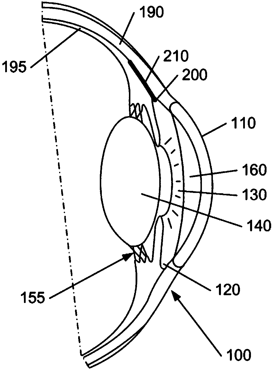
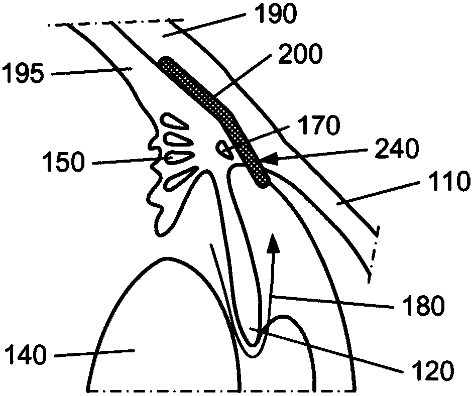
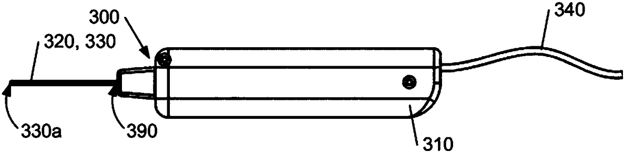
[0068]The present invention relates to a system comprising a single-use "minimally invasive" implant or deployment device from which an intraocular shunt device or implant is deployed into the suprachoroidal space—that is, the The space between the sclera and the choroid—in, or deployed into the subconjunctival space—the space between the conjunctiva and sclera of the eye. The intraocular shunt device or implant is preloaded within and released from a portion of the implant or deploy device, as will be described in more detail below. In one embodiment, the implanted or deployed device is singl...


PUM


Abstract

Described herein is an ocular implant system in which an implant (200) is deployed in a posterior space of the eye, for example, the suprachoroidal space or the subconjunctival space or the intrascleral space, with an access within the anterior chamber (160) for reducing intraocular pressure therein. The shunt (200) is implanted using an implantation device comprising a hollow shaft (330) mountedover a fixed shaft (320). The shunt (200) is located in a distal end of the hollow shaft (330) and adjacent a distal end of the fixed shaft (320), the distal end of the fixed shaft being located at aposition behind the distal end of the hollow shaft. Once the distal end of the hollow shaft (330) with the shunt (200) is located at the desired depth within the posterior space, the hollow shaft is withdrawn over the fixed shaft towards the proximal end thereof to leave the shunt in the posterior space with an access within the anterior chamber (160).

Description

technical field [0001] The present invention relates to ocular implant systems, and more particularly, but not exclusively, to devices for delivering ocular implants to predetermined locations in the eye. Background technique [0002] The mammalian eye consists of an anterior chamber located between the cornea, iris, and lens. This anterior chamber is filled with a fluid called aqueous humor. A trabecular meshwork consisting of many tiny channels is located in the corner between the iris and cornea. In a normal human eye, aqueous humor is produced at a constant rate—typically about 2.2 to 2.7 microliters per minute (μl / min)—by the ciliary body behind the iris. In the conventional outflow pathway, this aqueous humor flows between the lens and iris and is then drained through the trabecular meshwork and returned to the circulatory system. [0003] The intraocular pressure (IOP) to maintain this outflow from normal eyes tends to remain in the range of 10 mmHg to 20 mmHg. Ho...

Claims


Application Information

Patent Timeline
Patent Type & Authority Applications(China)
IPC IPC(8): A61F9/00
CPCA61F9/00781A61F9/0017A61B90/39A61F2230/0008A61F2250/0097A61F2230/0069A61B2090/3941A61F2210/0071A61B17/3468
Inventor 尼古拉斯·万迪斯特埃米利亚诺·德马尔科塞西尔·罗伊
Owner ISTAR MEDICAL
Why Eureka
Try Eureka