Double-chemical-treatment sewage treatment tank

A sewage treatment tank and chemical treatment technology, applied in water/sludge/sewage treatment, multi-stage water treatment, filtration treatment, etc., can solve the problems of long time, high cost, limited sewage treatment capacity, etc.

Inactive Publication Date: 2018-08-24
登封绿芝松农业科技有限公司
View PDF0 Cites 0 Cited by
  • Summary
  • Abstract
  • Description
  • Claims
  • Application Information

AI Technical Summary

Problems solved by technology

[0002] With the increasing awareness of environmental protection, the country's policies on environmental protection and convenience have become more stringent, and sewage treatment has been raised to a new level. There are not only floating objects and solid waste in sewage, but also toxic and harmful elements. However, the existing sewage treatment Generally, civil engineering is used to build fixed buildings such as sewage treatment canals and sewage treatment pools, which is not only costly and time-consuming, but also once the construction is completed, there is no possibility of changing the place. There is no problem for the sewage treatment of some large chemical enterprises, but for small It is very inconvenient for enterprises or for the scene of temporary sewage treatment on site; in addition, many existing sewage treatment devices have quite limited treatment capacity for sewage. The reason is that the chemicals were not mixed well in the sewage and the reaction time of the chemicals did not reach their full reaction

Method used


Image

  • Double-chemical-treatment sewage treatment tank
  • Double-chemical-treatment sewage treatment tank

Examples


Embodiment Construction

[0018] The following will clearly and completely describe the technical solutions in the embodiments of the present invention with reference to the accompanying drawings in the embodiments of the present invention. Obviously, the described embodiments are only some, not all, embodiments of the present invention. Based on the embodiments of the present invention, all other embodiments obtained by persons of ordinary skill in the art without making creative efforts belong to the protection scope of the present invention.

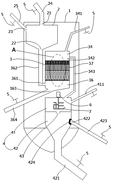
[0019] like Figure 1-2 As shown, the double chemical treatment sewage treatment tank includes a tank body 1, and the tank body 1 is provided with a pre-chemical reaction chamber 2, a floating filter device 3, and a reaction separation chamber 4 sequentially from top to bottom. The pre-chemical reaction chamber 2 includes sewage Inlet 22, sewage outlet and chemical substance inlet 23, sewage inlet 22 is connected with sewage inlet pipe 24, chemical substance i...


PUM


Abstract

The invention relates to a double-chemical-treatment sewage treatment tank. A tank body is internally provided with a front-positioned chemical reaction cabin, a floating filtering device and a reaction and separation cabin, wherein the front-positioned chemical reaction cabin comprises a sewage inlet, a sewage outlet and a chemical substance inlet; the floating filtering device comprises upper, middle and lower cabins; a plurality of floating filler filtering layers are arranged between upper and lower filtering screens; the lower cabin is provided with a liquid inlet; the sewage outlet is communicated with the liquid inlet through a liquid inlet pipe; the upper part of the upper cabin is connected with a backwashing pipe; a backwashing dreg discharging opening is formed in the bottom ofthe lower cabin; a filtered water outlet is formed in the side edge of the upper cabin; the reaction and separation cabin comprises a post-positioned chemical reaction cabin and a solid-liquid separation cabin at the lower part; one side of the post-positioned chemical reaction cabin is connected with a chemical substance feeding pipe which obliquely extends upward; the bottom of the solid-liquidseparation cabin is connected with a sediment discharging pipe; the solid-liquid separation cabin is further provided with a clean water discharging opening; a filtering baffle plate covers the cleanwater discharging opening; each pipe is provided with a control valve. The double-chemical-treatment sewage treatment tank has the advantages of simple structure, convenience for movement, conveniencefor dismounting and mounting and better treatment effect.

Description

technical field [0001] The invention relates to a dual chemical treatment sewage treatment tank. Background technique [0002] With the increasing awareness of environmental protection, the country's policies on environmental protection and convenience have become more stringent, and sewage treatment has been raised to a new level. There are not only floating objects and solid waste in sewage, but also toxic and harmful elements. However, the existing sewage treatment Generally, civil engineering is used to build fixed buildings such as sewage treatment canals and sewage treatment pools, which is not only costly and time-consuming, but also once the construction is completed, there is no possibility of changing the place. There is no problem for the sewage treatment of some large chemical enterprises, but for small It is very inconvenient for enterprises or for the scene of temporary sewage treatment on site; in addition, many existing sewage treatment devices have quite lim...

Claims


Application Information

Patent Timeline
Patent Type & Authority Applications(China)
IPC IPC(8): C02F9/04
CPCC02F9/00C02F1/001C02F2301/08
Inventor 王变芳
Owner 登封绿芝松农业科技有限公司
Why Eureka
Try Eureka