A concrete composite beam structure

A technology of combining beams and concrete, applied in bridges, bridge construction, bridge parts, etc., can solve the problems of bridge deck rupture or corrosion, affecting the service life of bridges, uneconomical, etc., to avoid pressure and burden, save procurement costs, improve The effect of work efficiency

Active Publication Date: 2019-09-06
山东建业建设发展集团有限公司
View PDF1 Cites 0 Cited by
  • Summary
  • Abstract
  • Description
  • Claims
  • Application Information

AI Technical Summary

Problems solved by technology

[0002] Conventional steel-concrete composite beams are structures composed of exposed steel beams or steel truss beams and reinforced concrete slabs through connectors. This type of bridge has the advantages of fast construction speed, small building height, and good seismic performance. It is widely used in the construction of buildings, highways and urban bridges. Due to the continuous increase of traffic volume and heavy vehicles, coupled with the impact of the environment, the conventional steel-concrete composite beams appear longitudinal cracking of reinforced concrete wing plates and reinforcement bars soon after operation. Concrete bridge deck transverse cracking, partial cracking or corrosion of bridge deck, steel girder corrosion and other diseases seriously affect the service life of the bridge. It is prone to damage under the influence of the environment and the environment, which reduces the service life. Ultra-high performance concrete (UHPC) is made of fine sand as aggregate, mixed with a large amount of mineral admixtures such as silica fume, high-efficiency water reducer and fine steel fibers. A high-strength, high-durability, high-toughness, dense concrete material. Compared with ordinary concrete, coarse aggregates (stones) are eliminated. It is a high-performance concrete composed of fine-grained dense materials and fiber-reinforced materials. The compressive strength and tensile strength are much higher than ordinary concrete. Although UHPC has good performance, the cost is much higher than ordinary concrete. It would be uneconomical to use UHPC for the bridge deck. In the existing technology, for example The invention patent with the application number 201520410112.4 includes several steel beams arranged side by side, and the first ultra-high performance concrete layer, the first ordinary concrete layer, the second ultra-high performance concrete layer, and the second ordinary concrete layer are arranged between the two steel beams. layer and ultra-high-performance concrete surface layer, the first ultra-high-performance concrete layer, the first ordinary concrete layer, the second ultra-high-performance concrete layer, the second ordinary concrete layer and the ultra-high-performance concrete surface layer are arranged in sequence from bottom to top , the upper part of the steel beam is provided with a connecting part, the end of the first ultra-high performance concrete layer and the end of the first ordinary concrete layer are connected to the connecting part, and the second ultra-high performance concrete layer is also connected by shear resistance The parts are connected with the connecting part. Although the structure of the invention is simple, there are many deficiencies and defects. In the existing equipment, there are defects in the design of the first ordinary concrete layer and the second ultra-high performance concrete layer. The first ordinary concrete layer The joint with the second ultra-high-performance concrete layer lacks fixing devices, the connection effect between the steel beam and the ground is not good, collapse has occurred, and the stability performance is poor. In view of these situations, in order to avoid the above-mentioned technical problems, it is necessary to provide a Composite beam structure of concrete to overcome said defects in the prior art

Method used


Image

  • A concrete composite beam structure
  • A concrete composite beam structure
  • A concrete composite beam structure

Examples


Embodiment Construction

[0020] The following will clearly and completely describe the technical solutions in the embodiments of the present invention with reference to the accompanying drawings in the embodiments of the present invention. Obviously, the described embodiments are only some, not all, embodiments of the present invention. Based on the embodiments of the present invention, all other embodiments obtained by persons of ordinary skill in the art without making creative efforts belong to the protection scope of the present invention.

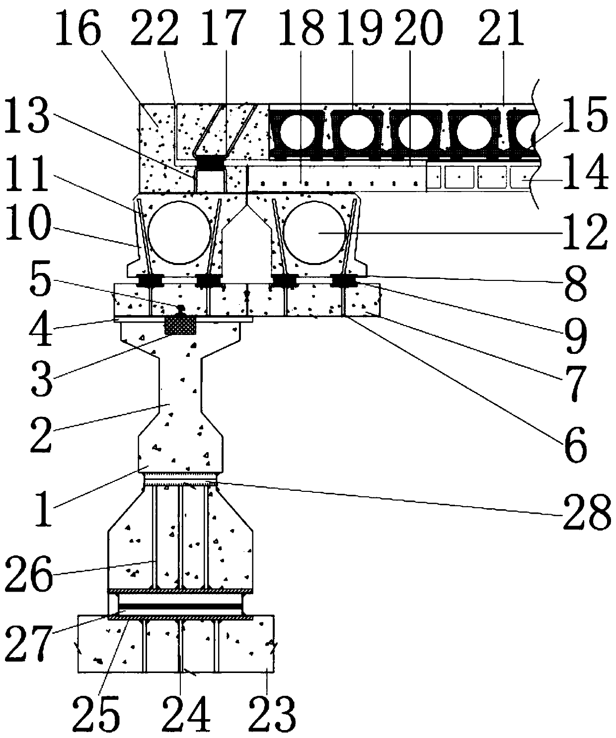
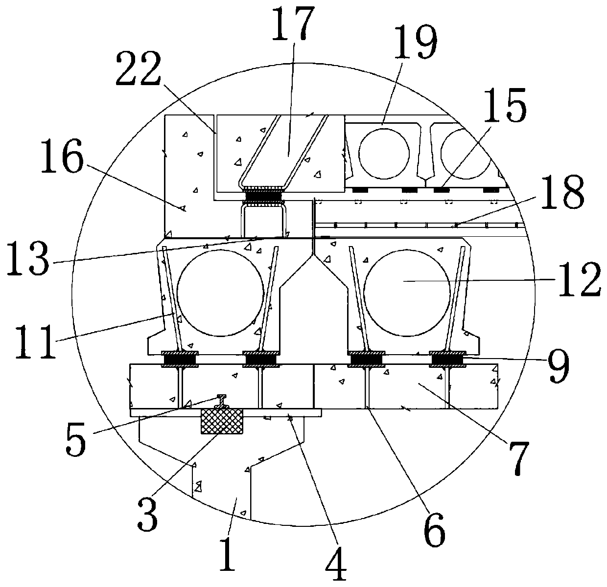
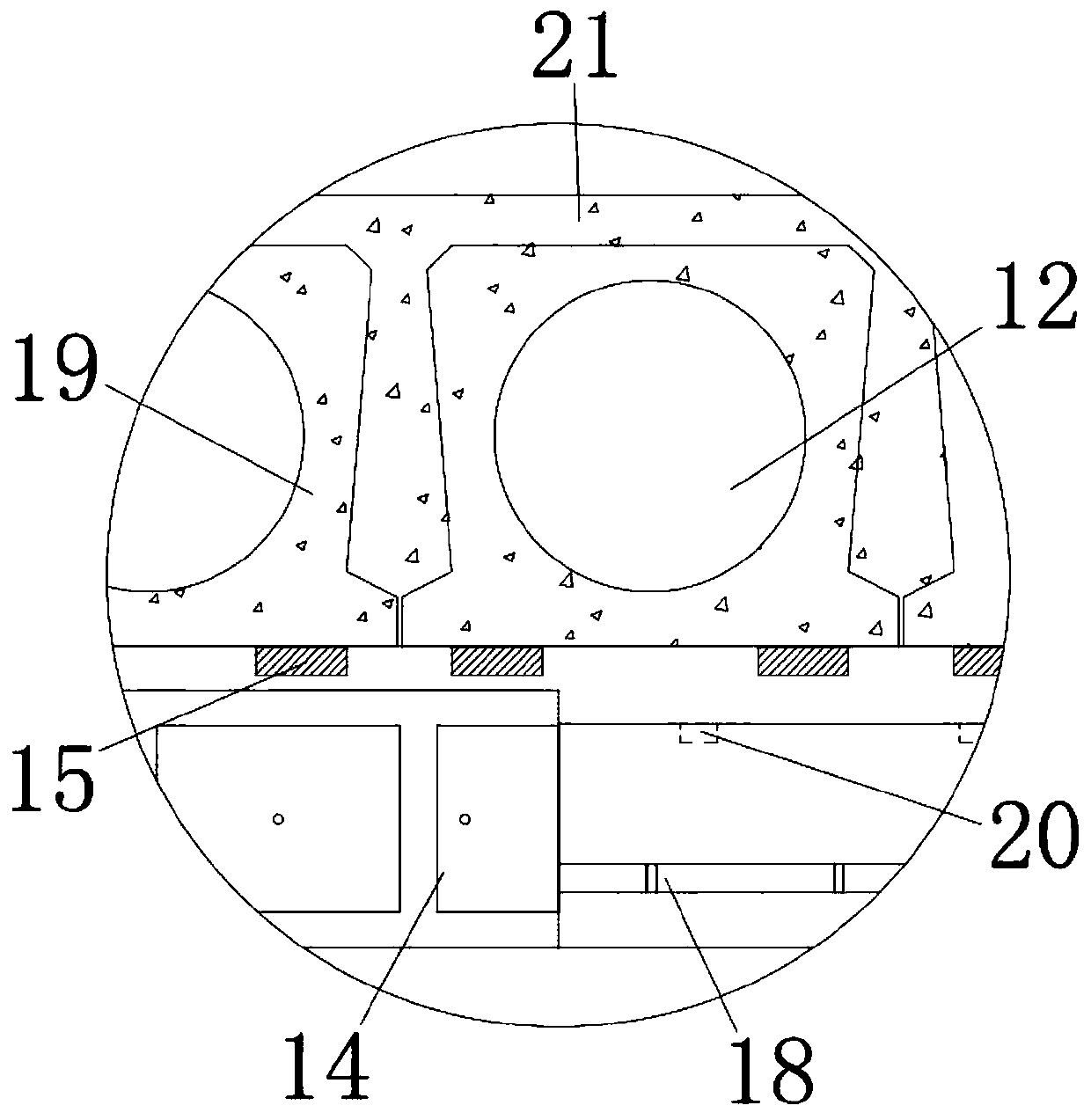
[0021] see Figure 1-4, the present invention provides a technical solution: a concrete composite beam structure, including a leg 1 for installing and fixing a fixed block 3, and a horizontal plate 28 is installed on the lower surface of the leg 1 for connecting the leg 1 and Fixed rod 26, the upper surface of horizontal plate 28 links to each other with the lower surface of support leg 1, and the lower surface of horizontal plate 28 is equipped with fixed rod...


PUM


Abstract

The invention discloses a concrete composite beam structure. The concrete composite beam structure includes a supporting leg, a concrete base is arranged on the inner wall of the supporting leg, and the outer wall of the concrete base is connected with the inner wall of the supporting leg. A fixed block is installed on the inner wall of the supporting leg, and the outer wall of the fixed block isconnected with the inner wall of the supporting leg. An underboarding is installed on the outer wall of the fixed block, the inner wall of the underboarding is connected with the outer wall of the fixed block, and an inserting core is installed on the upper surface of the fixed block. According to the concrete composite beam structure, through the cooperation of the supporting leg, the concrete base, the fixed block and the underboarding, work pressure and burden caused by frequent adjustment and maintenance during use is avoided, existing concrete composite beam structures can also be more recognized in the market, the construction quality of the concrete composite beam structure is improved, the purchase cost of construction enterprises is saved, waste of construction engineering resources is avoided, and the concrete composite beam structure is suitable for application and popularization.

Description

technical field [0001] The invention relates to the technical field of civil engineering, in particular to a concrete composite beam structure. Background technique [0002] Conventional steel-concrete composite beams are structures composed of exposed steel beams or steel truss beams and reinforced concrete slabs through connectors. This type of bridge has the advantages of fast construction speed, small building height, and good seismic performance. It is widely used in the construction of buildings, highways and urban bridges. Due to the continuous increase of traffic volume and heavy vehicles, coupled with the impact of the environment, the conventional steel-concrete composite beams appear longitudinal cracking of reinforced concrete wing plates and reinforcement bars soon after operation. Concrete bridge deck transverse cracking, partial cracking or corrosion of bridge deck, steel girder corrosion and other diseases seriously affect the service life of the bridge. It ...

Claims


Application Information

Patent Timeline
Patent Type & Authority Patents(China)
IPC IPC(8): E01D2/00E01D19/00
Inventor 陆养忠陈璇杨斌
Owner 山东建业建设发展集团有限公司
Why Eureka
Try Eureka