Pressurizing device and method of unpressurized oil cylinder

A booster device and booster oil cylinder technology, which is applied in fluid pressure actuators, accumulator devices, and fluid pressure actuation system tests, can solve the problem that the booster pressure build-up time is greatly affected and the pressure build-up time is insufficient To meet the problems of satisfaction and delayed pressure build-up time, etc., to achieve the effect of novel design, fast pressure build-up, and improved yield

Pending Publication Date: 2018-08-24
NINGBO HAITIAN METAL MOLDING EQUIP CO LTD
View PDF0 Cites 3 Cited by
  • Summary
  • Abstract
  • Description
  • Claims
  • Application Information

AI Technical Summary

Problems solved by technology

The most important of these is the "fast Supercharging” section, the connection process of this section requires the PLC to receive the position and pressure signals, and then the PLC outputs the signal to the booster solenoid valve coil after reaching the set value, and the solenoid valve coil pushes the solenoid valve spool to drain the control oil after the solenoid valve coil responds. At this time, the spool of the cartridge valve starts to respond. After the cartridge valve responds, it pushes the booster cylinder to start to move. During this process, the pressure generated by the booster cylinder and the direction of liquid flow are used to close the high and low pressure valves. During this process All actions require a certain response time, so that the time from the end of rapid injection to the actual start of boosting is delayed, resulting in a delay in the pressure building time of boosting, which seriously affects the actual action response time of pressure building
[0004] For the parameter of pressure build-up time, the shorter the better, but limited to the impact of the structure of the pressurization method of the current die-casting machine, the booster pressure build-up time is greatly affected by external factors
For the current production technology needs, the pressure building time of 30ms is not enough to meet some precision casting products; therefore, in order to improve the performance requirements of the machine, we need to make a further improvement plan on the pressurization method of the traditional die casting machine

Method used


Image

  • Pressurizing device and method of unpressurized oil cylinder

Examples


Embodiment Construction

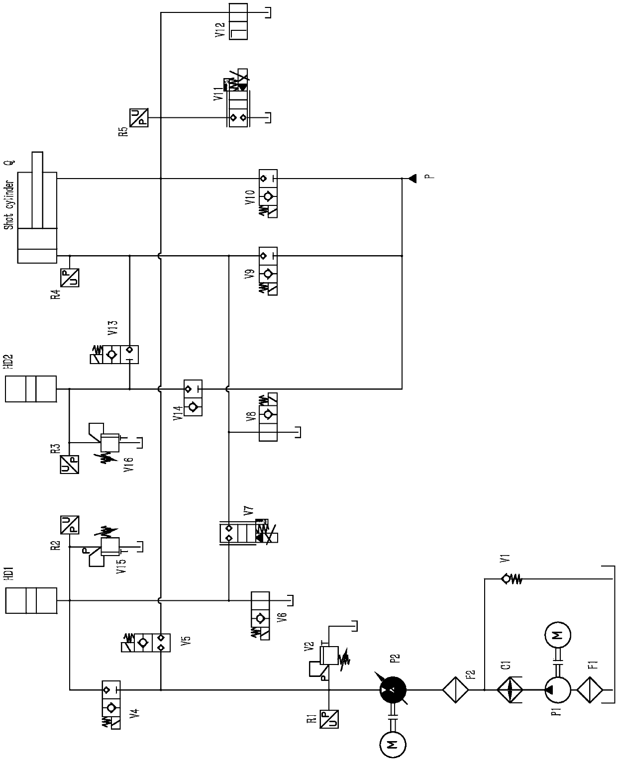
[0030] Such as figure 1 As shown, a booster device without a booster cylinder, including injection cylinder (Q), hammer front valve (V9), hammer rear valve (V10), low-pressure pump set (P1), high-pressure variable pump set (P2), HD1 energy storage valve (V4), high-pressure accumulator (HD1) and fast accumulator (HD2); the front end of the injection cylinder (Q) is provided with a hammer front valve (V9), and the hammer front valve (V9 ) is connected with a fast accumulator (HD2), the rear end of the injection cylinder (Q) is provided with a hammer rear valve (V10), and the hammer rear valve (V10) is connected with a P-end oil supply port, and the P The end oil supply port is connected to the fast accumulator (HD2); the low-pressure pump group (P1) is connected to the high-pressure variable pump group (P2), and the high-pressure variable pump group (P2) is connected to the HD1 energy storage valve (V4 ), the HD1 accumulator valve (V4) is connected with a high pressure accumula...


PUM


Abstract

The invention discloses a pressurizing device and method of an unpressurized oil cylinder. The device comprises an injection oil cylinder, a low-pressure pump set, a high-pressure variable pump set, ahigh-pressure energy storing device and a rapid energy storing device, wherein a hammer front valve is arranged at the front end of the injection oil cylinder and is connected to the rapid energy storing device; a hammer rear valve is arranged at the rear end of the injection oil cylinder and is connected to a P end oil supplying port; the P end oil supplying port is connected to the rapid energystoring device; the low-pressure pump set is connected to the high-pressure variable pump set which is connected to an HD1 energy storing valve; and the HD1 energy storing valve is connected to the high-pressure energy storing device. The method comprises the steps of early-stage preparation of action of an injection part, first-stage low-speed action, second-stage low-speed action, high-speed action, pressurizing, following and hammer returning. The device is simple in structure; the pressure buildup time can be increased to be 12ms, so that the pressurizing performance of the injection partof a large die-casting machine can be extremely improved; the difficulty that the parameters of a die casting machine in the prior art cannot meet the requirements of some precision products on casting technologies can be solved; and the yield of products can be effectively increased.

Description

technical field [0001] The invention relates to a pressure building oil circuit system, in particular to a booster device and method for a non-pressurized oil cylinder. Background technique [0002] Die-casting machine is one of the commonly used machines in the machinery industry. It is used to apply high-pressure die-casting to metal products, so the pressure build-up time and parameters are very important. The current national standard stipulates that the pressure building time for large machines is 25-30ms, but in fact the pressure building time of die casting machine manufacturers is above 30ms. [0003] The injection action process of the die-casting machine is generally: a slow speed two-stage slow fast pressurized Hold pressure follow out Hammer back Injection complete. The most important of these is the "fast Supercharging” section, the connection process of this section requires the PLC to receive the position and pressure signals, and then the PLC...

Claims


Application Information

Patent Timeline
Patent Type & Authority Applications(China)
IPC IPC(8): F15B1/02F15B21/04F15B19/00
CPCF15B1/024F15B19/00F15B21/042F15B2211/20584
Inventor 乐晓东徐建华郑培韦少宇胡宇黄新安
Owner NINGBO HAITIAN METAL MOLDING EQUIP CO LTD
Why Eureka
Try Eureka