Soaking plate

A vapor chamber and evaporating plate technology, applied in indirect heat exchangers, lighting and heating equipment, etc., can solve problems such as increased heat transfer resistance, difficult control of sintering quality, and large energy consumption

Pending Publication Date: 2018-08-24
GUANGDONG UNIV OF TECH
View PDF0 Cites 20 Cited by
  • Summary
  • Abstract
  • Description
  • Claims
  • Application Information

AI Technical Summary

Problems solved by technology

However, the working medium backflow of the existing flat heat pipe mainly depends on the capillary force provided by the liquid-absorbing core, and the capillary limit and boiling limit of heat transfer are relatively small. In addition, due to the existence of the liquid-absorbing core, the liquid working medium condensed near the condensation surface cannot be returned immediately However, the liquid-absorbent wick near the condensation surface increases the heat transfer resistance. In addition, the structure of the sintered liquid-absorbent core itself consumes a lot of energy, and the sintering quality is difficult to control.

Method used


Image

  • Soaking plate
  • Soaking plate
  • Soaking plate

Examples


Embodiment Construction

[0026] The following will clearly and completely describe the technical solutions in the embodiments of the present invention with reference to the accompanying drawings in the embodiments of the present invention. Obviously, the described embodiments are only some, not all, embodiments of the present invention. Based on the embodiments of the present invention, all other embodiments obtained by persons of ordinary skill in the art without making creative efforts belong to the protection scope of the present invention.

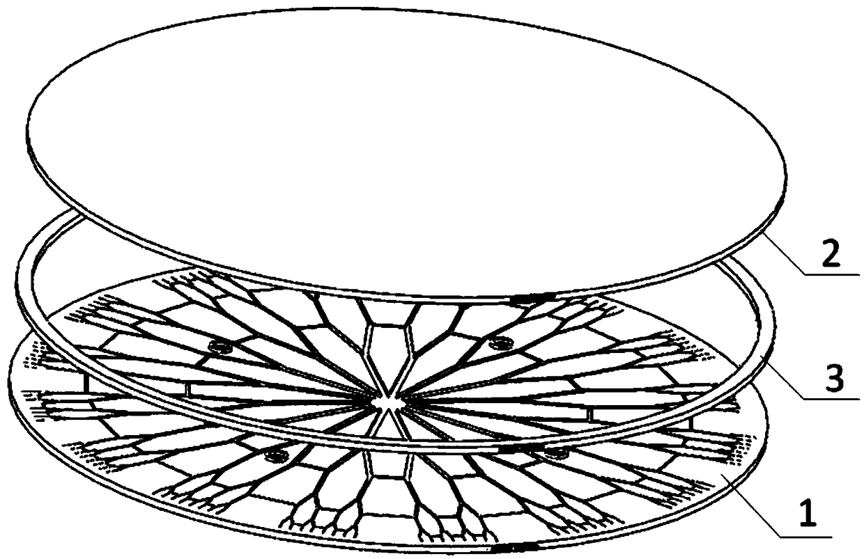
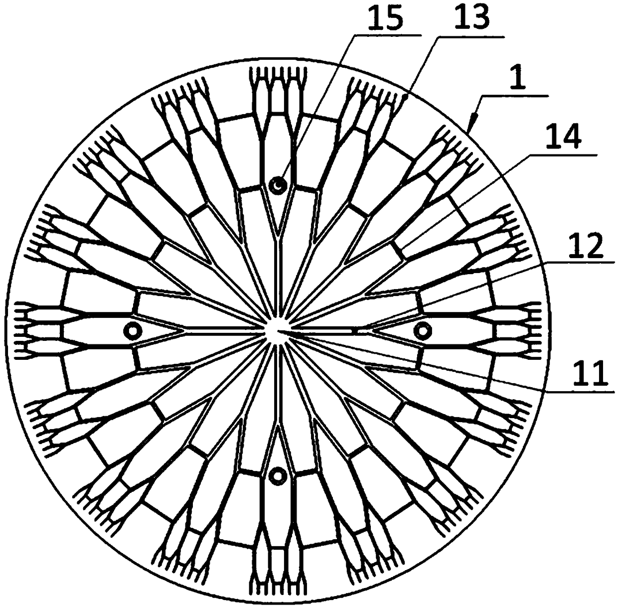
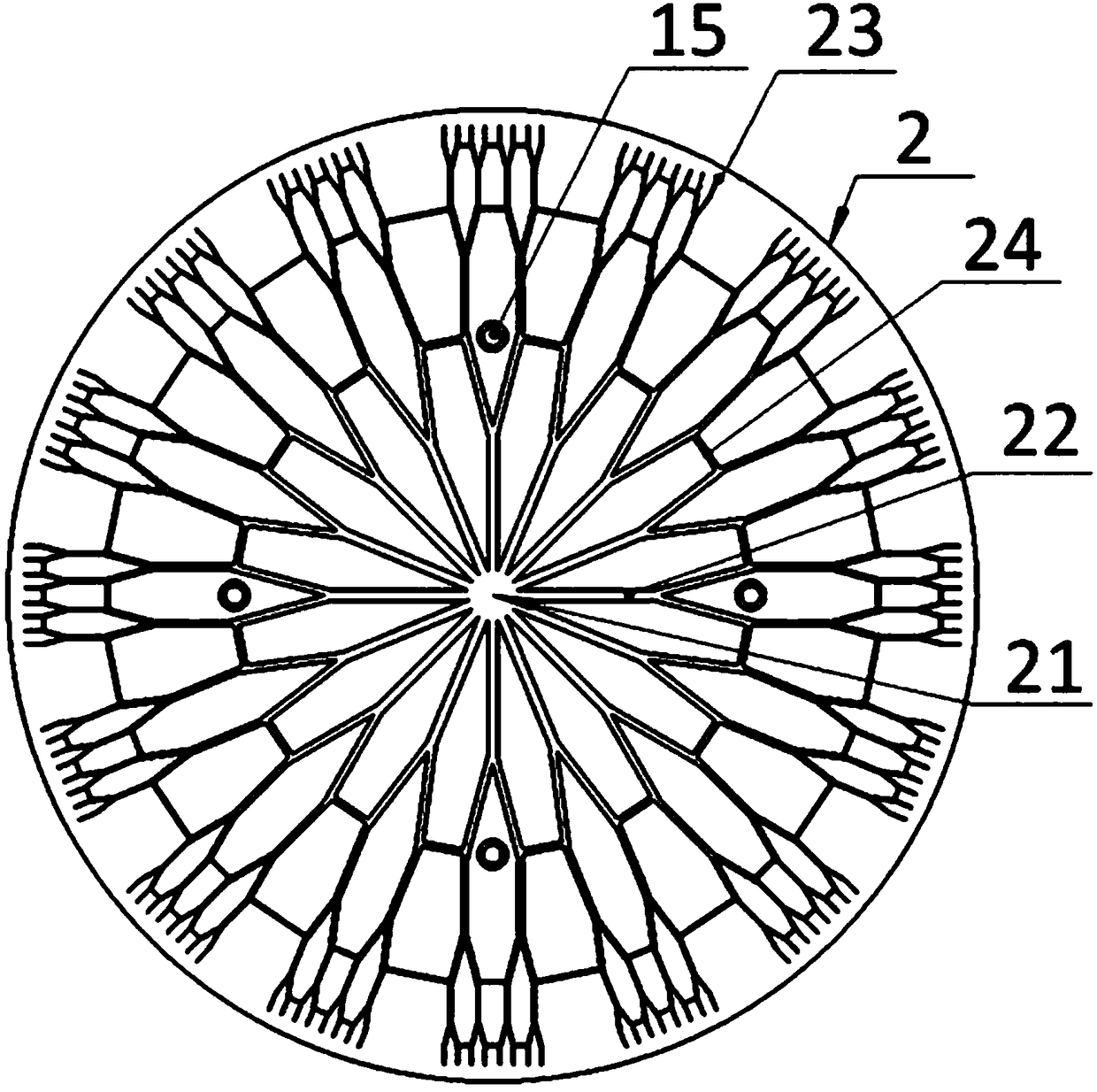
[0027] Please refer to figure 1 , figure 2 and image 3 , figure 1 An exploded view of the overall structure of a specific embodiment provided by the present invention; figure 2 for figure 1 The schematic diagram of the structure of the evaporation plate shown; image 3 for figure 1 The schematic diagram of the structure of the condensation plate is shown.

[0028] In a specific embodiment provided by the present invention, the vapor chamber mainly in...


PUM


Abstract

The invention discloses a soaking plate comprising an evaporation plate, a condensation plate and a connecting plate. The evaporation plate directly faces the condensation plate. The connecting plateis used for connecting the evaporation plate with the condensation plate so as to form a closed cavity, and the closed cavity is filled with a working medium. The evaporation plate is provided with channels for conveying the working medium, and the channels are distributed in the circumferential direction of the evaporation plate and are divergent from the center to the edge of the evaporation plate. According to the soaking plate, the evaporation plate and the condensation plate are provided with bionic vein polygon micro-channel structures, the wall faces of the channels of the evaporation plate and the periphery of support columns are covered with lyophilic liquid sucking cores, thus the wall faces have lyophilic performance, capillary performance of the channel liquid sucking cores isimproved, and liquid sucking speed of the channel liquid sucking cores is increased. The wall faces of the channels of the evaporation plate and the periphery of the support columns are covered with lyophilic materials, liquid spreading is achieved progressively from the edge to the center of the condensation plate, the downward circulation speed of the working medium in main channels is increased, a working medium backflow path is shortened, working medium backflow speed is increased, and heat dissipation benefits are increased.

Description

technical field [0001] The invention relates to the technical field of heat dissipation of microelectronic devices, in particular to a vapor chamber. Background technique [0002] With the rapid development of electronic packaging technology, the integration and performance of electronic chips continue to improve, resulting in a continuous increase in chip power. At present, the average heat flux density on the chip surface has exceeded 100W / cm 2 , and tends to continue to increase. At the same time, after the chip package is completed, there are generally "hot spots" with high local heat, which will lead to a sharp rise in the local temperature of the chip and affect the stability of the chip. [0003] Solutions to chip failure due to temperature rise include not only conventional cooling methods such as air cooling, liquid cooling, and heat pipes, but also new cooling methods such as semiconductor cooling, micro-jet technology, liquid metal heat dissipation, and carbon f...

Claims


Application Information

Patent Timeline
Patent Type & Authority Applications(China)
IPC IPC(8): F28D15/02F28D15/04
CPCF28D15/0233F28D15/04F28D2021/0029
Inventor 王长宏赵雨亭黄浩东田中轩马瑞鑫
Owner GUANGDONG UNIV OF TECH
Why Eureka
Try Eureka