Optical elasticity test method

An elastic testing and optical technology, applied in material analysis, measuring devices, scientific instruments, etc. through optical means, can solve the problems of long processing time, low accuracy, and collecting a large amount of data, and achieve shortened test time and small loading range , the effect of reducing the amount of calculation

Active Publication Date: 2018-08-24
TIANJIN UNIV
View PDF10 Cites 4 Cited by
  • Summary
  • Abstract
  • Description
  • Claims
  • Application Information

AI Technical Summary

Problems solved by technology

Chinese patent CN106073824A discloses shear wave ultrasonic elastography, which uses acoustic radiation force to generate shear waves and detects them through ultrasonic imaging technology. This technology has low resolution and cannot reach histological resolution, and has low sensitivity to mechanical information. Detection of small deformations is not conducive to early diagnosis of diseases
US20170107558 uses acoustic radiation to generate shear waves, and US20170290503 US20170290503 uses air impulses to generate shear waves. The experimental devices and controls of these two methods are relatively complicated and have poor practicability; the shear wave velocity extraction algorithm is based on continuous shear waves Loading requires a large amount of data collection, long processing time and low accuracy
[0004] To sum up, the related methods based on ultrasonic imaging have low technical resolution, and the existing optical coherent elastic technology adopts continuous wave loading, which not only takes a long time to bear force on the object to be tested, but also requires a large amount of data to be processed, and the experimental device and control are also difficult. quite complicated

Method used


Image

  • Optical elasticity test method
  • Optical elasticity test method
  • Optical elasticity test method

Examples


Embodiment 1

[0036] Embodiment A pair of test of the elastic modulus of biological tissue analog body

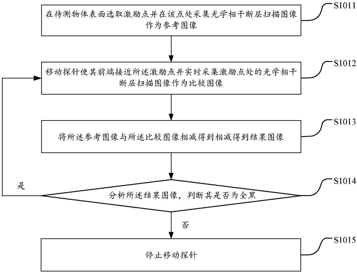
[0037] In order to ensure that the probe does not cause damage to the surface of the object to be measured during the operation, it is necessary to adjust the probe to make it perpendicular to the surface of the object to be measured before the shear wave velocity test and make the front end of the probe touch the surface of the object to be measured without acting on the surface of the object to be measured. The surface of the object, that is to say, make the tip of the probe just touch the surface of the object to be measured. Such as image 3As shown, the method of subtracting the optical coherence tomography images can be used to judge whether the probe has just touched the surface of the object to be measured: the image at the excitation point when the probe is not in contact with the surface of the object to be measured is collected by optical coherence tomography As a reference i...

Embodiment 2

[0049] Embodiment two is to the test of the modulus of elasticity of the isolated chicken liver sample

[0050] Select the excitation point on the surface of the isolated chicken liver sample as the first excitation point, and select a detection point within 10 mm from the surface of the excitation point, and the distance between the detection point and the excitation point does not need to be measured. After the probe is set at the initial position, the position of the probe is adjusted through the three-dimensional mobile stage combined with the real-time image of the above-mentioned optical coherence tomography, so that the probe is perpendicular to the surface of the chicken liver and the front end of the probe is aligned with the isolated chicken liver sample to be tested The surface is just in contact, and the setting of the contact between the probe and the isolated chicken liver sample adopts the method of real-time subtraction of the optical coherence tomography image,...

Embodiment 3

[0056] Embodiment 3 In vivo skin elastic modulus test of human body

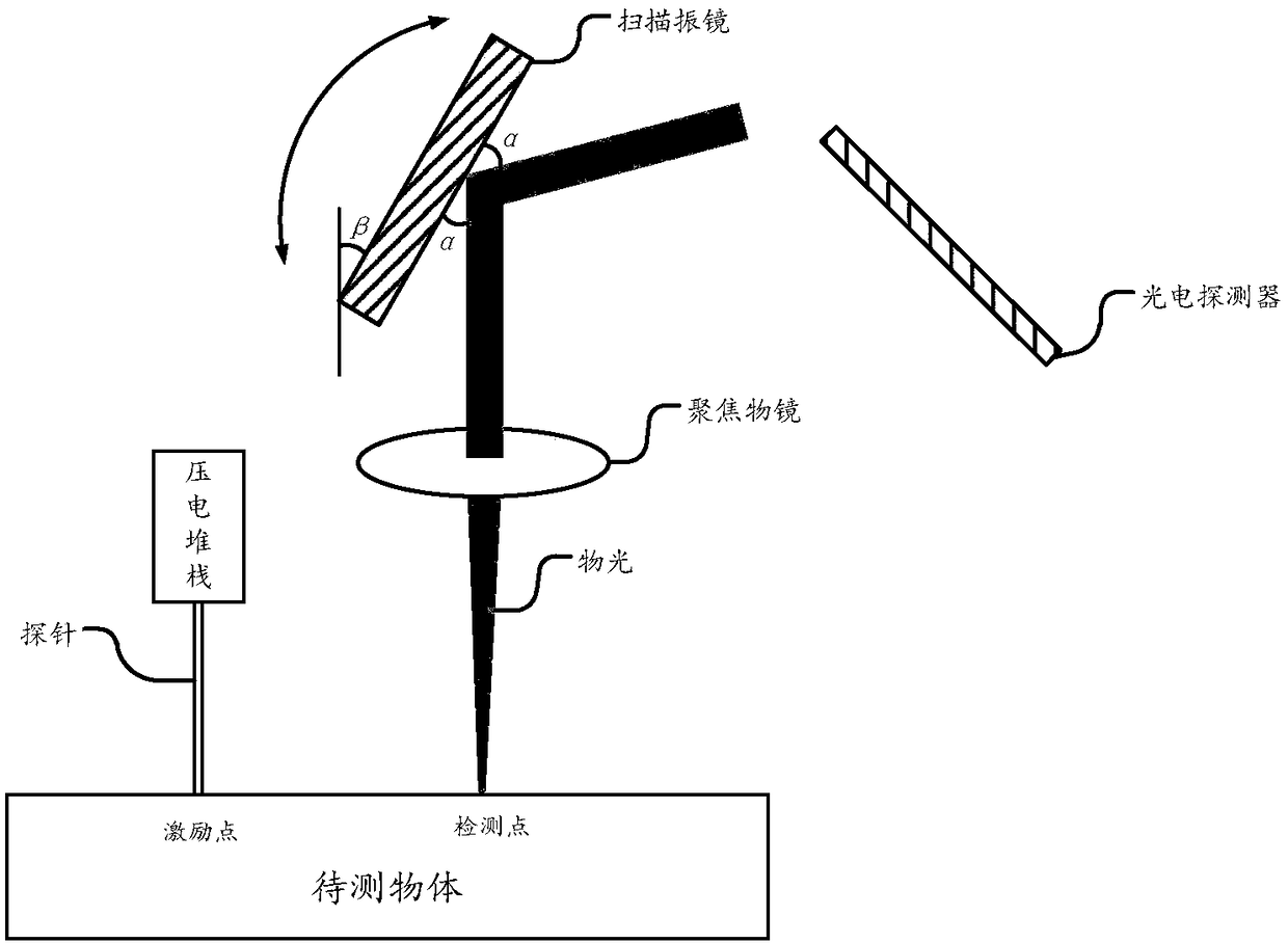
[0057] In this embodiment, the finger pulp skin test is described. Firstly, the probe tip is placed in the area to be tested on the finger pulp, and the probe tip is adjusted to maintain slight contact with the finger pulp skin at the excitation point through a three-dimensional moving table. Then focus the optical coherence tomography object light beam on any point within 10 mm from the excitation point on the surface of the finger as the first detection point. 1ms in advance so that the shear wave information can be collected. After the probe is set to be in proper contact with the skin of the finger pulp, the piezoelectric stack is started to load the shear wave on the skin of the finger pulp through the probe; after the optical coherence tomography signal is collected at the first detection point, the control such as figure 1 The scanning galvanometer shown is rotated to move the optical coherence tomog...


PUM

PropertyMeasurementUnit
densityaaaaaaaaaa
shear modulusaaaaaaaaaa
densityaaaaaaaaaa

Abstract

The invention provides an optical elasticity test method including the following steps: 1) generating a shear wave, which is propagated with an exciting point as center to all around, and collecting an optical coherence tomography signal at any one point on the surface of a to-be-tested object nearby the exciting point; 2) processing the OCT signal to obtaining propagation speed of the shear wavein the to-be-tested object; 3) calculating elasticity modulus of the to-be-tested object according to the propagation speed. The method is small in loading amplitude and short in time and is free of damaging the to-be-tested object. The propagation time of the shear wave is extracted through phase analysis, so that the propagation speed of the shear wave is calculated accurately, thus obtaining the elasticity modulus of the to-be-tested object. The calculation load is greatly reduced and test time is shortened.

Description

Background technique [0001] The mechanical properties of biological tissues are an important indicator to reflect the health of their physiological conditions. Some tissues have obvious differences in elastic modulus between pathological and healthy states. Quantitative testing of the elastic modulus of biological tissue is very important for the research, diagnosis and treatment of the occurrence and development of diseases. [0002] Optical Coherence Tomography (OCT) uses near-infrared coherent light interference to generate high-resolution images, which can realize real-time detection and imaging of living tissues without radiation or damage. Optical coherence tomography has been widely used in the detection of clinical ophthalmic diseases, and it is also more and more widely used in cardiovascular and other fields. Optical coherence elastography (OCE) collects signals through optical coherence tomography when the measured tissue is deformed under load, and obtains mechani...

Claims


Application Information

Patent Timeline
Patent Type & Authority Applications(China)
IPC IPC(8): G01N29/04G01N29/07G01N21/00
CPCG01N21/00G01N29/041G01N29/07
Inventor 孙翠茹张小艺陈金龙
Owner TIANJIN UNIV
Why Eureka
Try Eureka