A High Voltage DC Optical Harmonic Measurement Device

A measurement device, high-voltage direct current technology, applied in the field of harmonic measurement devices and optical dual-channel harmonic current measurement devices, can solve problems such as difficult to meet harmonic measurement requirements, improve detection accuracy and performance, and reduce electromagnetic interference Influence, improve the effect of demodulation speed and feedback stability

Active Publication Date: 2021-01-12
BEIJING SIFANG JIBAO AUTOMATION
View PDF11 Cites 0 Cited by
  • Summary
  • Abstract
  • Description
  • Claims
  • Application Information

AI Technical Summary

Problems solved by technology

Accurate measurement of harmonic information is the basis and premise of harmonic monitoring and governance. The Chinese national standard GB / T20840.8-2007 Transformer Part 8: Electronic current transformer requires that the quality measurement ratio difference of the 50th harmonic is less than 5%, the angular difference is less than 5°, and the traditional current transformer is technically difficult to meet the above harmonic measurement requirements due to the limitation of the principle

Method used


Image

  • A High Voltage DC Optical Harmonic Measurement Device
  • A High Voltage DC Optical Harmonic Measurement Device
  • A High Voltage DC Optical Harmonic Measurement Device

Examples


Embodiment Construction

[0033]The technical solution of the present invention will be described in further detail below in conjunction with the accompanying drawings of the specification.

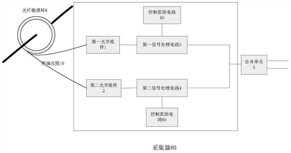
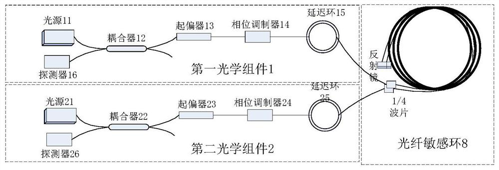
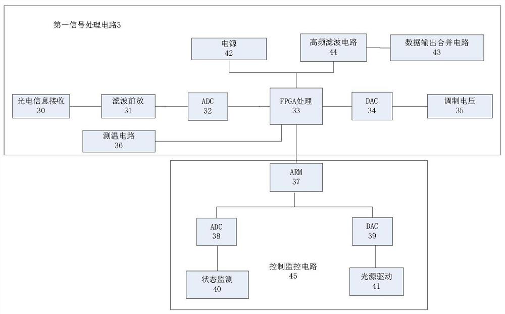
[0034]As attachedfigure 1 Shown is a schematic diagram of the structure of the high-voltage DC optical harmonic measurement device of the present invention. The high-voltage DC optical harmonic measurement device disclosed in the present invention includes a dual optical path fiber sensitive ring 8, a first optical component 1, a second optical component 2, The first signal processing circuit 3, the second signal processing circuit 4, the first control monitoring circuit 45 (attachedfigure 1 ,3In the control monitoring circuit 45), the second control monitoring circuit 65 (attachedfigure 1 ,4In the control and monitoring circuit 65), the merging unit 5.

[0035]The dual-optical fiber sensitive ring 8 is sleeved on the DC current-carrying conductor, and the two-channel harmonic current output data of the dual-optical fiber sen...


PUM


Abstract

A high-voltage DC optical harmonic measuring device is disposed on a DC current carrying conductor through a double-optical-path fiber sensitive ring. The two pieces of harmonic current output data ofthe double-optical-path fiber sensitive ring are connected to the input end of a first optical component and the input end of a second optical component through two polarization maintaining optical cables respectively. The output end of the first optical component is connected to the input end of a first signal processing circuit. The output end of the second optical component is connected to theinput end of a second signal processing circuit. The output data of the first signal processing circuit and the second signal processing circuit are connected to the input end of a merging unit. A first control monitoring circuit and a second control monitoring circuit are also connected to the first signal processing circuit and the second signal processing circuit respectively. The high-voltageDC optical harmonic measuring device solves the bottleneck problem of the transfer characteristic of conventional high harmonic collection, meets the 4kHz sampling rate requirement of low-order harmonic protection metering devices and the 50kHz sampling rate requirements of high-order harmonic protection and power quality metering devices.

Description

Technical field[0001]The invention belongs to the technical field of electrical measurement, and relates to a harmonic measurement device, in particular an optical dual-channel harmonic current measurement device used in the field of high-voltage direct current transmission and transformation.Background technique[0002]With the development and progress of society, a large number of power electronic devices and non-linear loads are connected to the power grid system, and the resulting power harmonics cause the deterioration of power quality. Power harmonics have a serious impact on the safe and stable operation of the power grid. Since the DC grid contains a large number of power electronic devices and nonlinear loads, this will cause a large amount of harmonic currents to be injected into the grid and cause the grid voltage to be distorted. These devices are the harmonic sources of the power system. The harmonic sources in DC power systems mainly include: various rectifier equipment,...

Claims


Application Information

Patent Timeline
Patent Type & Authority Patents(China)
IPC IPC(8): G01R23/17
CPCG01R23/17
Inventor 孟祥强刘海锋李秦张超叶艳军秦红霞
Owner BEIJING SIFANG JIBAO AUTOMATION
Why Eureka
Try Eureka