
A damage control external fixator

An external fixation and plate fixation technology, applied in the field of medical surgical instruments, can solve the problems of unsatisfactory intramedullary nail technology compatibility, external fixation stability not as good as steel plate fixation, inconvenient surgical operation, etc., to avoid soft tissue iatrogenic damage and The effect of infection risk, reduction of bleeding and secondary injury, and high clinical promotion value

Active Publication Date: 2020-12-01
李莉
View PDF9 Cites 0 Cited by
  • Summary
  • Abstract
  • Description
  • Claims
  • Application Information

AI Technical Summary

Problems solved by technology

However, there are many problems in the traditional external fixation technology, so its clinical application has been questioned
First, the structure of the traditional external fixator device is complicated, and the installation and operation procedures are cumbersome; second, the bone needle track of the external fixator communicates with the skin around the fracture, which may cause deep infection and even osteomyelitis; third, the external fixator Bone needles need to be placed percutaneously, which may further aggravate the damage of the skin and soft tissue around the fracture. Fourth, the distribution of bone needles in traditional external fixation technology is relatively scattered, and the compatibility with plate minimally invasive internal fixation and intramedullary nailing technology is not ideal. Internal fixation treatment for patients who have been fixed will be hindered by the space of the bracket, and the operation is inconvenient
[0004] The distribution of spicules in the existing external fixation technology for bone injuries is scattered, mainly because the stability of external fixation is not as good as that of plate fixation, so it is necessary to implant multiple spicules into the diaphysis and epiphysis to ensure the stability of the system
And if the span at both ends is too long, the existing fixing brackets cannot be firmly fixed

Method used


Image

  • A damage control external fixator
  • A damage control external fixator
  • A damage control external fixator

Examples


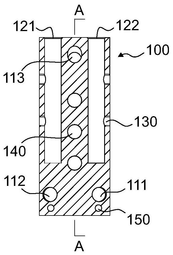
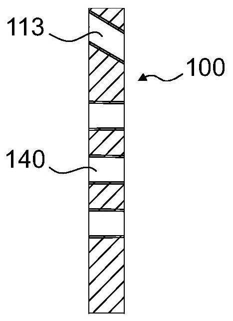
Embodiment 1

[0030] Such as figure 1 As shown, a damage control external fixation bracket includes a proximal fixation plate 100 , a calcaneus fixation plate 200 , two pairs of carbon connecting rods 400 , and two chucks 500 .

[0031] Please refer further figure 2 and image 3 As shown, the near-end fixing plate 100 is provided with three nail holes 111, 112, 113 distributed in the shape of "pin", with a diameter of 5.0 mm, and internal threads are provided, and the two nail holes 111, 112 are arranged on the left and right at the proximal end. distribution, the axes of the two are offset toward the midline; the remaining third nail hole 113 is located at the distal end, and its axis is offset toward the proximal end. The distal side of the proximal fixing plate 100 is provided with two grooves 121 , 122 in the proximal direction, and the connecting rod 400 can be accommodated in the grooves. After the connecting rod 400 is inserted, fastening screws can be screwed into the side locki...

Embodiment 2

[0035] Please base on figure 1 , Figure 8 shown, combined with Figure 6 and Figure 7 , the proximal fixing plate 100, the connecting rod 400, the chuck 400 and their connection methods in this embodiment are the same as those in Embodiment 1. The difference is that the calcaneal fixation plate 200 which is also the distal end fixation plate is replaced by the tibial fixation plate 300 .

[0036]The tibial fixation plate 300 is provided with three nail holes 310, and the centers of the upper openings of the three nail holes are located on the midline of the tibial fixation plate 220, but since the axes of the three nail holes are not parallel to each other, the centers of the lower openings of the three nail holes are not on the center line of the tibia fixation plate 220. on the same straight line. The tibial fixation plate 220 is provided with grooves 320 from the proximal end to the distal end. The grooves 320 are distributed on the left and right sides of the midline...


PUM


Abstract

The invention discloses an injury control external fixator, comprising a proximal fixing plate, a distal fixing plate, a plurality of connection rods and a plurality of clamps. The proximal fixing plate and the distal fixing plate are provided respectively with a plurality of screw holes having an internal thread, and grooves for fitting the connection rods; each clamp includes an upper clamping portion and a lower clamping portion; the clamps enable the connection rods on the proximal fixing plate and the distal fixing plate to be jointly fixed to a point. The injury control external fixatorhas the advantages that higher structural rigidity is gained via the use of single-side long-span structure, surgical fixation is simple to perform, a limb with severe injury can be quickly stabilized, and hemorrhage and secondary injury can be lessened; screws are mounted on the fixator far away from the injured part, so that iatrogenic injury and infection risk of soft tissues due to traditionalscrew holes can be avoided; the fixator is well compatible with steel plates, intramedullary nails and otherness in terms of internal fixation and is highly worthy of clinical popularization.

Description

technical field [0001] The invention relates to the field of medical operation instruments, in particular to a damage control external fixation bracket. Background technique [0002] Open fractures of the tibia and fibula caused by high-energy injuries, the limbs are extremely unstable, the soft tissues and main blood vessels and nerves are in a high-risk state or have been damaged, and even on the verge of traumatic amputation. The most fundamental measures of limb salvage surgery are to quickly stabilize the limbs, protect the bones and soft tissues, establish a stable biomechanical environment as soon as possible to facilitate the repair of soft tissue injuries, reduce local traumatic inflammatory reactions through braking, effectively control wound bleeding, and maintain brain and kidney function. Effective circulatory perfusion of vital organs such as blood vessels, reducing the risk of systemic inflammatory reactions. Therefore, in the trauma first aid of high-energy ...

Claims


Application Information

Patent Timeline
Patent Type & Authority Patents(China)
IPC IPC(8): A61B17/64
CPCA61B17/6441A61B17/645A61B2017/603
Inventor 李颖
Owner 李莉
Learn More